|
|
|
Categories
|
|
Information
|
|
Featured Product
|
|
|
 |
|
|
There are currently no product reviews.
 ;
Great quality manual, fast service, excellent seller... Thanks !!!
;
Great manual and fast service. Download was possible after a few hours.
;
thanks a lot.
without the service manual my handycam was going to the trash.
good job, go on.
bye
 ;
This service manual is a good copy of the original, complete and fully readable. It is really useful to repair my Tv set following its clear instructions.
;
Excellent quality. Easy process to download. No issues or problems at all - was exactly what I was looking for and needed. Great service.
SJ-58L-T2 SJ-63L-T2 SJ-68L-T2
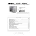
2 Replacing Handles and Door Parts
1. Remove Screw caps and Screws on each door handle, then remove the handles. Flatten the surface of the screw holes using the handle of a screwdriver, etc., then mount 3 units of F (Door hole covers) on each door. 2. Remove the Nylon bearings, Door stopper(Lower door only), Stopper springs on the right side of each door and the cap on the left side of the Upper door. Furthermore, open the hidden holes on the bottom of the door using a screwdriver, then remove a screw (Lower door only). 3. Remove Screw caps and Screws on the right side of each door, then remove the Door cap covers and mount D and E (Door cap covers) on the left side. 4. Replace Nylon bearings to the left side of each door, then mount the Upper door cap on the right side. Furthermore, mount Door stopper and B and C(Stopper springs) on the left side as well. Screw in a screw in the screw hole on the lower right of the Lower door. 5. Fix upper portion of Upper handle using one screw on the right side of Lower door, then temporarily fix the handle to the door using tape. 6. To open screw holes, first make marks on the doorplate surface through the 3 holes of the handle, then temporarily remove the handle (make sure that the dimensions of the markings are as shown in the diagram). 7. Lightly dent the center of each marking, then open holes using a 3.8 mm drill bit. Use a drill guide, etc., to prevent the drill bit from entering more than 5 mm. Make sure to open the hole straight. Opening the hole in an angle will cause the handle to clatter. The door will be unusable if the hole are too large or too deep or if the screws are tightened too much. 8. Mount the handle using the 4 screws and install Screw caps. 9. Mount Lower handle on the right side of Upper door by repeating steps 5. ~ 8. above.
2
F
12
4
2
5,6
16mm 27mm
3 1 3 4 4
172mm 172mm
D B
2 3
2
7
E
3 11
5mm
8
(J) F
2 4 2 4 2
5-8 9
C
Figure M-2
22
|
|
|
> |
|