|
|
|
Categories
|
|
Information
|
|
Featured Product
|
|
|
 |
|
|
There are currently no product reviews.
 ;
Great manual, great price. Has a few of the basic operating instructions that most service manuals leave out. Complete instructions for disassembling board by board, safety precautions, schematics, complete parts list.
;
I am very pleased with the service manual for my RT-909. This was an easy purchase and great procuct, and much cheaper than other venues i had looked at. This web site is now listed in my favorites list. KEEP UP THE GOOD WORK. THANKS. J. BROWN
;
A very well written and easy to understand manual.
;
There was no problem at all.After paying i had to wait only a few hours,than i could
download the manual in best pdf-quality.
Thank You !
 ;
I found this service manual to be complete in every detail except for troubleshooting charts. It would be helpful if it had a set of troubleshooting charts; however it is a very good manual otherwise and for the price it is very well worth it.
SJ-58L-T2 SJ-63L-T2 SJ-68L-T2
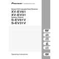
2 Replacing Handles and Door Parts
1. Remove Screw caps and Screws on each door handle, then remove the handles. Flatten the surface of the screw holes using the handle of a screwdriver, etc., then mount 3 units of F (Door hole covers) on each door. 2. Remove the Nylon bearings, Door stopper(Lower door only), Stopper springs on the right side of each door and the cap on the left side of the Upper door. Furthermore, open the hidden holes on the bottom of the door using a screwdriver, then remove a screw (Lower door only). 3. Remove Screw caps and Screws on the right side of each door, then remove the Door cap covers and mount D and E (Door cap covers) on the left side. 4. Replace Nylon bearings to the left side of each door, then mount the Upper door cap on the right side. Furthermore, mount Door stopper and B and C(Stopper springs) on the left side as well. Screw in a screw in the screw hole on the lower right of the Lower door. 5. Fix upper portion of Upper handle using one screw on the right side of Lower door, then temporarily fix the handle to the door using tape. 6. To open screw holes, first make marks on the doorplate surface through the 3 holes of the handle, then temporarily remove the handle (make sure that the dimensions of the markings are as shown in the diagram). 7. Lightly dent the center of each marking, then open holes using a 3.8 mm drill bit. Use a drill guide, etc., to prevent the drill bit from entering more than 5 mm. Make sure to open the hole straight. Opening the hole in an angle will cause the handle to clatter. The door will be unusable if the hole are too large or too deep or if the screws are tightened too much. 8. Mount the handle using the 4 screws and install Screw caps. 9. Mount Lower handle on the right side of Upper door by repeating steps 5. ~ 8. above.
2
F
12
4
2
5,6
16mm 27mm
3 1 3 4 4
172mm 172mm
D B
2 3
2
7
E
3 11
5mm
8
(J) F
2 4 2 4 2
5-8 9
C
Figure M-2
22
|
|
|
> |
|