|
|
|
Categories
|
|
Information
|
|
Featured Product
|
|
|
 |
|
|
There are currently no product reviews.
 ;
The manual is useful for trouble shooting for an old instrument. It saved money,and let me enjoy DIY.
 ;
Perfect source of information for replacing the HDD and performing general diagnostics.
;
Perfect source of information for replacing the HDD and performing general diagnostics.
;
Very good scanned copies. Quick response and reasonable price. Thanks for service!
;
Good. Good. Good. Good. Good. Good. Good. Good. Good. Good. Good. Good. Good. Good.
SJ-P58M/58M SJ-P63M/63M SJ-P68M/68M
(3) Setting of Fan motor ass'y , Defrost thermo. ass'y and Fuse ass'y
E.V cover Tapping screw
E.V cover sealer C
E
L-band C
Lead E.Vcover ass�y more than 3.5mm more than 3.5mm Tapping screw Aluminum tape
Defrost thermo. ass�y
E Set metal side below
[FRONT SIDE]
Aluminum tape
Take out lead wire from square hole to front, and seal with E.V cover sealer C.
F
F
Fuse ass�y Defrost thermo. ass�y
ATTENTION
cut
E.V cover Fuse ass�y
Turn up is lead wire
Not come out of claw
Sec. F-F
Sec. E-E
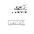
Figure A-17 (4) Inserting of pins
Fan motor 1 , 2
WIRE COLOR FOR FAN MOTOR
F-thermostat 3 (RED, inserted)
100-110V : WHITE 127V : YELLOW 220-240V : BLUE
F-thermostat 4 (BROWN, inserted) Defrost thermo. 5 (PINK) Defrost thermo. 6 (BLUE)
1 4
2 5
3 6
Fan motor 9 Fuse 8 (WHITE) Fuse 7 (BLACK)
10 5mm
7
8
9
Note
Pins should be inserted surely, and check by pulling it.
Figure A-18
After inserting, fix with vinyl tape.
Vinyl tape
60 m m
Figure A-19
25
+
L-band C
|
|
|
> |
|