|
|
|
Categories
|
|
Information
|
|
Featured Product
|
|
|
 |
|
|
There are currently no product reviews.
 ;
This is a great site. I placed my order and by the next am it was available for download. Had some problems with some missing copy on some pages. Once I brought the error to the OMC's attention, the issue was resolved. I'll come back again.
 ;
Mi spiace per non poter scrivere in inglese... ma sono veramente soddisfatto del servizio offerto. Grazie..!!
;
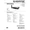
The quality of this manual is good. It has all schematics and setup information for both the MDS-B3 and the MDS-B4. The scan quality is quite good, all pages are readable, This service manual also contains scans of the operating instructions from the User manual.
;
Quick site processing. A complete and very useful manual with all details. Thank you!
;
Das Service Manual war von der ersten bis zur letzten Seite sehr informativ und hilfreich. Die Darstellung aller Teile war klar und der Text gut lesbar.
Vielen Dank, das war nicht der letzte Download bei ownner-manuals.com.
3. SERVO SYSTEM CHECK 3-1. RF Switching Position Adjustment (MA-341 Board) [Adjustment Purpose] To adjust the link of the A-ch and B-ch of the tape playback outputs. To make the unit compatible with other tapes and units. If this specification is not satisfied, the link will appear on the screen and the screen will be disrupted, etc. Mode Signal Measurement point Playback Alignment tape: SP color bar portion CH1: CN270 pin 2 (PB RF) CH2: CN270 pin 3 (RF SWP) Oscilloscope REMOCON CH+/� A=minimize
4. AUDIO SYSTEM ADJUSTMENT � Adjust both L ch and R ch. [Connecting Instruments]
Audio line OUTPUT L/R Audio line INPUT L/R Audio oscillator 600 � Attenuator VTR Audio level meter or distortion meter 47 k�
Measuring instrument Adjusting element Specified value
Fig. 6-2-4
4-1. Hi-Fi Audio System Adjustment (Hi-Fi model only) � Perform the adjustment setting the switch on the following positions. � AUDIO MONITOR ..................................................... STEREO [Adjustment Method] 1. ACE head adjustment.....Refer to the VHS mechanical adjustment manual (S MECHANISM)(9-921-647-11). 2. E-E output level check 3. �Recording Bias Adjustment�
[Adjustment Method] 1) Playback the alignment tape. 2) Short JS401 to Ground. 3) Check that �A P� is indicated on FL display. 4) Adjust so that part A becomes minimized at CH +/�. 5) Write data in EEPROM by pressing PAUSE button. Monoral model: 6) The display �A P� disappears and then the Adjustment mode terminates. Hi-Fi model: 6) The display changes to �A H� and the mode goes to the HiFi switching position Adjustment.
A CH1 PB RF CH2 RF SWP
Fig. 6-2-3
6-3
|
|
|
> |
|