|
|
|
Categories
|
|
Information
|
|
Featured Product
|
|
|
 |
|
|
There are currently no product reviews.
 ;
As Always you can find here manuals even of difficult TV scheme which are scan in almost perfect way.clear and fast!!!!!
Great work thanks!
;
Incredibly clear!!!! Well done, complete and wonderful. It could not better than this!!!!
 ;
Thank You for fast delivery for the sheme.
Everything allright.
Thanks & best regards Franz
;
again you did a very good job. It was fast too. Photocopy are really readable and clear
;
Probably it never existed a 1081 official service manual from Commodore, it's look more like a NAPCEC service manual & diagrams compilation of the 1084 series and his variants, like the nap6523, 8cm505, 1084S, 1084P and obviously the 1081. It's more complete than other scans and the quality of the scans also are far superior. It has two circuit diagrams variants of the 1081, mono and stereo versions. It doesn't include a diagram for the Philips CM8500 or CM8501, they look like the 1081 but they are slightly different.
2-4-2.
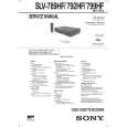
Hi-Fi Switching Position Adjustment (MA-342 Board) [Adjustment Purpose] To adjust the link of the A-ch and B-ch of the tape playback outputs. To make the unit compatible with other tapes and units. If this specification is not satisfied, the link will appear on the screen and the screen will be disrupted, etc. Mode Signal Measurement point Measuring instrument Adjusting element Specified value Playback Alignment tape: SP color bar portion CH1: CN270 Pin 1 (HF ADJ) CH2: CN270 Pin 3 (RF SWP) Oscilloscope Remote Commander CH +/� B=minimize
2-4-3. Normal Audio System Adjustment � Make adjustment in the SP mode unless otherwise specified. Use a normal VHS cassette for an adjustment tape. � Set AUDIO MONITOR to normal. 2-4-4. ACE Head Adjustment Refer to the VHS mechanical adjustment manual MECHANISM) (9-921-647-11).
(S
2-4-5. E-E Output Level Check [Adjustment purpose] Confirm that the output level adjust the reference input is within the specification. Mode Signal Measurement point Measuring instrument Specified value E-E 400 Hz, �7.5 dBs CJ561 L/R Audio level meter �7.5 ± 2 dBs
[Adjustment Method] 1) Check that �A H� is indicated on FL display. 2) Adjust so that part B becomes minimized at CH +/�. 3) Write data EEPROM by pressing PAUSE button. 4) Check that �A H� indicator turns off. 5) If �A H� indicator is still on, restart RF switching position Adjustment from the beginning.
B
[Check Method] 1) Input signal of 400 Hz and �7.5 dBs to the CJ561 L/R. 2) Check that the audio output level is �7.5 ± 2 dBs. 2-4-6. Frequency Response Check [Adjustment purpose] Confirm that the frequency characteristic is within the specification. Mode REC and PB (SP mode) Signal Measurement point Measuring instrument Specified value 400 Hz, �27.5 dBs 7 kHz, �27.5 dBs CJ561 L/R Audio level meter 0 ± 3 dB
CH1 HFADJ CH2 RF SWP
Note: Tape path adjustment must have been completed.
Fig. 6-2-5
[Confirmation Method] 1) Supply a signal of 400 Hz, �27.5 dBs to CJ561 L/R. 2) Connect the audio level meter to CJ561 L/R. 3) Adjust the attenuator so that the audio level meter will indicate �27.5 dBs. 4) Make recording in the SP mode. 5) Set an audio line input signal to 7 kHz and make recording. 6) Playback a recorded portion, and measure output levels at 400 Hz and 7 kHz. 7) Confirm that the 7 kHz playback output level within a range of the 400 Hz playback output level 0 ± 3 dB.
6-4
|
|
|
> |
|