|
|
|
Categories
|
|
Information
|
|
Featured Product
|
|
|
 |
|
|
There are currently no product reviews.
 ;
Very helpfull information and I highly recommend this source for needed information about your products.
 ;
More than pleased with my prurchase, very good product for the price.
;
This is a good quality scan of the service manual which includes an assembly diagram, block diagram, schematic, and parts list. Exactly what is needed to repair my KR-V55R receiver.
;
Excellent concise manual. All needed information was included. Typeface and diagrams were clear. Very fair price considering what others are charging. Many thanks
;
Response is a little slow- I had to wait 12 hours to receive download link but it says that it may take up to 24hrs.
Manual is old and was not produced in PDF- scanned copy is exellent.
Overall- value for money- I recommend
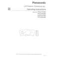
3-16.CRESCENT SLIDE (See Figs. 3-16-1 and 3-16-2)
1) Refer to section 3-2 and remove the mechanism unit. When you do this, make sure the mechanism is in EJECT mode. 2) Refer to section 3-3-1 and remove the cassette mechanism assembly. 3) Refer to section 3-7-2 and remove the capstan brake assembly. 4) Refer to section 3-12-4 and remove the T soft brake assembly. 5) Refer to section 3-13-1 and remove the T brake act slide. 6) Refer to section 3-12-1, then remove the reel belt and the reel pulley. 7) Refer to section 3-15, then remove the wheel gear 2 and the main cam. 8) Refer to section 3-13-2, then remove the wheel gear 1 and the brake control lever. 9) Remove the two screws !¡, then remove the crescent mounting !�. 10) Remove the clamps 1 and 2, then raise the right end of the crescent slide 3 slightly. Slide the crescent slide 3 to the right until it comes away from the clamp 4, then remove it.
3 Crescent slide 5 Hole 2 Clamp A 1 Clamp
!¡ Screw
!� Crescent mounting
7 Hole 9 Hole D 8 Pin
6 Hole 4 Clamp
0 Pin
Fig. 3-16-1
Apply grease to the areas shown in � The places marked by dots should be greased particularly generously.
ASSEMBLY NOTES:
1. Apply grease (VHJ-0100) to the points A, B, C and D in Fig. 3-16-1, and to the crescent slide 3 shown in Fig. 3-16-2. 2. Before fitting the crescent slide 3, refer to section 3-133 and align the arrow on the S brake act slide with the arrow on the mechanism chassis. Then refer to Fig. 317-3 and check that the S load gear and the T load gear have completed tape unloading. 3. When assembling the parts, raise the right side of the crescent slide 3 slightly, and keeping it in this position, slot the left side into the clamp 4, then align the hole 5 with the hole 6 in the mechanism chassis. When you do this, check that the hole 7 is aligned with the pin 8 on the BT spring lever assembly, and that the hole 9 is aligned with the pin 0 on the S brake act slide, before pressing the crescent slide 3 into place. Check that the clamps 1, 2 and 4 are engaged. 4. After assembly, check that each leverand each brake is working properly.
Grease the sides Grease the teeth Crescent slide
Fig. 3-16-2
5-23
|
|
|
> |
|