|
|
|
Categories
|
|
Information
|
|
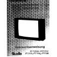
Featured Product
|
|
|
 |
|
|
There are currently no product reviews.
 ;
We received the manual in a timely manner and it was exactly what we were expecting. Excellent replacement for original Service Manual.
All schematics are very legible. We are really satisfied.
;
Fast delivery and good quality manual.
Very easily downloadable from a given url.
Will be pleased to buy again from this seller.
;
Ottimo manuale, grafica ferfetta invio rapidissimo. Altissimo livello!!!!!
;
Great PDF easy to read good info needed for replacment of belts and assembly and specs.
;
complete and unabridged very good quality
easy to download.
recieved in two days.
2-3.
2-3-1.
SERVO SYSTEM Adjustment
2-4.
VIDEO SYSTEM ADJUSTMENT
RF Switching Position Adjustment (MA-314 Board) Purpose: Adjust the interval between A ch and B ch of tape playback output. Improve the interchangeability with other tapes and sets. When it is out of order, the interval appears on the screen, the screen is disturbed. Mode Signal Measurement Point PB Alignment tape SP mode color bar CH1: VIDEO LINE OUT CH2: Pin 2 of CN262 (RF SWP) Oscilloscope 6.5 ± 0.5 H (416 ± 32 µsec)
Adjust the video system in the following sequence as a rule. The color video signal supplied from the pattern generator is used as a video input signal for video system adjustment in the recording mode. Make sure that sync. and color burst signals meet requirements specified at set up of adjustment shown in Fig. 7-2-1. [Adjustment Sequence] 2-4-1. Playback Y Signal Level Check 2-4-2. Recording Chroma Level Check 2-4-3. Sync. AGC Check 2-4-4. X�tal Oscillation Frequency Check 2-4-1. Playback Y Signal Level Check (MA-314 Board)
Measuring Instrument Specified Value
Purpose: Confirm that the playback Y signal level is correct. Mode Signal Measurement point Measurement equipment Specified value PB Alignment tape SP color bar Pin #� IC201 Oscilloscope 2.10 ± 0.18 Vp-p
Adjusting Method: 1) Connect MA-314 board Pin 5 of CN262 to the GND for about 1 secont to activate the RF switching position adjustment mode. 2) Check appear �A P� on FL display. 3) Using the channel + and � buttons, adjust to 416 ± 32 µsec (6.5 ± 0.5 H). 4) Press the pause button.
Confirmation Method: 1) Confirm that the play Y level is 2.10 ± 0.18 Vp-p.
CH1 CH2 Approx. 5 Vp-p V enargement Vertical sync. signal Approx. 1 Vp-p
White (100%)
2.10 ± 0.18 Vp-p
H
Fig. 7-2-4.
CH1
CH2
6.5 ± 0.5 H (416 ± 32 µsec)
Fig. 7-2-3.
7-3
|
|
|
> |
|