|
|
|
Categories
|
|
Information
|
|
Featured Product
|
|
|
 |
|
|
There are currently no product reviews.
 ;
The manual describes this product very good. It has the basic things to know and also a more detailed look. Very well made!
;
An excellent document to assist in the repair of my old personal tape player. It includes full circuit diagrams and physical layout drawings and full instructions on disassembly and fault finding.
Well worth the meagre price.
;
Very good conversation, Pretty fast Service, wood do it again,
Have paid by Paypal, so i got the Service Manual online after 15 Min.
Very helpfully.
Greeting from Germany,
Hans
;
Good-quality scans. Detailed description. I hope I can repair the machine.
;
High-quality scanning. Detailed description. Recommend for all technician. A+++
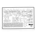
3-16.CRESCENT SLIDE (See Figs. 3-16-1 and 3-16-2)
1) Refer to section 3-2 and remove the mechanism unit. When you do this, make sure the mechanism is in EJECT mode. 2) Refer to section 3-3-1 and remove the cassette mechanism assembly. 3) Refer to section 3-7-2 and remove the capstan brake assembly. 4) Refer to section 3-12-4 and remove the T soft brake assembly. 5) Refer to section 3-13-1 and remove the T brake act slide. 6) Refer to section 3-12-1, then remove the reel belt and the reel pulley. 7) Refer to section 3-15, then remove the wheel gear 2 and the main cam. 8) Refer to section 3-13-2, then remove the wheel gear 1 and the brake control lever. 9) Remove the two screws !¡, then remove the crescent mounting !�. 10) Remove the clamps 1 and 2, then raise the right end of the crescent slide 3 slightly. Slide the crescent slide 3 to the right until it comes away from the clamp 4, then remove it.
3 Crescent slide 5 Hole 2 Clamp A 1 Clamp
!¡ Screw
!� Crescent mounting
7 Hole 9 Hole D 8 Pin
6 Hole 4 Clamp
0 Pin
Fig. 3-16-1
Apply grease to the areas shown in � The places marked by dots should be greased particularly generously.
ASSEMBLY NOTES:
1. Apply grease (VHJ-0100) to the points A, B, C and D in Fig. 3-16-1, and to the crescent slide 3 shown in Fig. 3-16-2. 2. Before fitting the crescent slide 3, refer to section 3-133 and align the arrow on the S brake act slide with the arrow on the mechanism chassis. Then refer to Fig. 317-3 and check that the S load gear and the T load gear have completed tape unloading. 3. When assembling the parts, raise the right side of the crescent slide 3 slightly, and keeping it in this position, slot the left side into the clamp 4, then align the hole 5 with the hole 6 in the mechanism chassis. When you do this, check that the hole 7 is aligned with the pin 8 on the BT spring lever assembly, and that the hole 9 is aligned with the pin 0 on the S brake act slide, before pressing the crescent slide 3 into place. Check that the clamps 1, 2 and 4 are engaged. 4. After assembly, check that each leverand each brake is working properly.
Grease the sides Grease the teeth Crescent slide
Fig. 3-16-2
5-23
|
|
|
> |
|