|
|
|
Categories
|
|
Information
|
|
Featured Product
|
|
|
 |
|
|
There are currently no product reviews.
 ;
very good manual with clear electrical schemes. Very helpful to find wat was wrong inside my microwave.
 ;
Hi, thankyou for providing the Nordmende Globetrotter original manufacturer's repair manual. Quality is very good and sharp - the PDF file was comfortably small to download. The only question is: why did it take so long to become ready for download?? Many thanks anyway, I fixed the fault in the radio thanks to the circuit.
regards: Nick
;
This was super service.Ordered this manual and was reading the download an hour later
;
as always, rapid and efficient, very good and clear prints
details clearly visible keep going this way!!!!!!
;
I expect a wonderful result as alaways!!!!!!
Usually is much faster....
2-4.
AUDIO SYSTEM ADJUSTMENTS
� Adjust both Lch and Rch. [Connection]
Audio generator 600 � Attenuator VCR Audio level meter or distortion meter 47 k�
CH1 RF SWP
OK CH2 NG
AUDIO LINE IN Feed signal both channelssimultaneously.
AUDIO LINE OUT
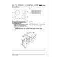
Fig. 7-2-4.
Hi-Fi Audio System Adjustment (SLV-ED60/ED70/EZ60/EZ70) � Set switches and knobs to the following positions to make adjustment unless otherwise specified. INPUT SELECT switch ................... LINE AUDIO MONITOR .......................... STEREO [Adjustment Sequence] 1. AF Switching Position Adjustment 2. Frequency Response Check 3. Overall Level Characteristic and Distortion Factor Check 4. Overall S/N Check 1. AF Switching Position Adjustment (MA-350 BOARD) Purpose: Adjust the interval between A CH and B CH of tape playback output. Improve the interchangeability with other tapes and sets. When it is out of order, noisy sound is increased and big noise is heard. Mode Signal Measurement point Measuring Instrument Specified Value PB Alignment tape SP mode color bar CH1: Pin 3 of CN203 CH2: Pin 1 of CN203 Oscilloscope Fig. 7-2-5 2-4-1.
Fig. 7-2-5.
2. Frequency Response Check Purpose: Confirm that the frequency characteristic is within the specification. Mode Signal REC and PB (SP, LP mode) 400 Hz, �7.5 dBs 20 Hz, �7.5 dBs 20 kHz, �7.5 dBs Audio output terminal Audio level meter 0 ± 2 dB
Measurement point Measurement equipment Specified value
Note: Tape path adjustment must have been completed. Confirmation Method: 1) Supply a signal of 400 Hz, �7.5 dBs to both L and R channels of Audio Line Input. 2) Connect the audio level meter to the Audio Line Output. 3) Adjust the attenuator so that the audio level meter will indicate �7.5 dBs. 4) Make recording. 5) Set an audio line input signal to 20 Hz and make recording. 6) Set an audio line input signal to 20 kHz and make recording. 7) Playback a recorded portion, and measure output levels at 400 Hz and 20 Hz and 20 kHz. 8) Confirm that the 20 Hz and 20 kHz playback output level within a range of the 400 Hz playback output level 0 ± 2 dB.
Adjusting Method: 1) Connect MA-350 board JS450 to the GND for about 1 second to activate the RF switching position adjustment mode. 2) Press the record button to activate the AF switching position adjustment mode. 3) Check appear �A H� on FL display. 4) Using the channels + and � buttons, minimize a chipped portion. At this time, confirm that a noisy sound is not heard. 5) Press the pause button.
7-3
|
|
|
> |
|