|
|
|
Categories
|
|
Information
|
|
Featured Product
|
|
|
 |
|
|
There are currently no product reviews.
 ;
It's a good manual, this one it's a scan from the original factory service manual, great quality 100% readeable. definetely it worths what I paid for.
 ;
A good manual! fast service and good qualityi for pdf document.
thanks!
;
Very helpful and complete manual. Maybe only one negative is schematics have sometimes unreadable name of the parts. But it's not a big problem.
;
Excellent high quality schematics brought my old Heidelberg back to life. Fast download at a reasonable price. Thanks.
;
This document is just what I was looking for, it´s very useful, it contains adjustment procedures for the final stage of the power amp and also
has a complete wiring diagram and description of the main semiconductors used in the design.
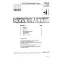
1. AF Switching Position Adjustment (MA-336 Board) [Adjustment Purpose] To adjust the link of the A-ch and B-ch of the tape playback outputs. To make the unit compatible with other tapes and units. If this specification is not satisfied, the link will appear on the screen and the screen will be disrupted, etc. Mode Signal Measurement point Measuring instrument Adjusting element Specified value Playback Alignment tape: SP color bar portion CH1: Pin 3 of CN101 CH2: Pin 1 of CN101 Oscilloscope RV201 Fig. 6-2-5
2-4-2. Normal Audio System Adjustment � Make adjustment in the SP mode unless otherwise specified. Use a normal VHS cassette for an adjustment tape. � Set AUDIO MONITOR to normal. 1. ACE Head Adjustment Refer to the VHS mechanical adjustment manual MECHANISM) (9-921-647-11).
(S
2. E-E Output Level Check [Adjustment purpose] Confirm that the output level adjust the reference input is within the specification. Mode Signal Measurement point Measuring instrument Specified value E-E 400 Hz, �7.5 dBs CJ461 L/R Audio level meter �7.5 ± 2 dBs
[Adjustment Method] 1) Playback the alignment tape. 2) Short-circuit between pins 1 and 2 of CN210. 3) Adjust RV201 to minimize a chipped portion. At this time, confirm that a noisy sound is not heard.
CH2 RF SWP
[Check Method] 1) Input signal of 400 Hz and �7.5 dBs to the CJ461 L/R. 2) Check that the audio output level is �7.5 ± 2 dBs. 3. Recording Bias Check [Adjustment purpose] Confirm that the frequency characteristic is within the specification. Mode REC and PB (SP mode) Signal 400 Hz, �27.5 dBs 7 kHz, �27.5 dBs Measurement point Measuring instrument Specified value Audio output terminal Audio level meter 0 ± 3 dB
OK CH1 REC AFM NG
Note: Tape path adjustment must have been completed.
Should be minimized RF signal dropout
Fig. 6-2-5
[Confirmation Method] 1) Supply a signal of 400 Hz, �27.5 dBs to both L and R channels of Audio Line Input. 2) Connect the audio level meter to the Audio Line Output. 3) Adjust the attenuator so that the audio level meter will indicate �27.5 dBs. 4) Make recording in the SP mode. 5) Set an audio line input signal to 7 kHz and make recording. 6) Playback a recorded portion, and measure output levels at 400 Hz and 7 kHz. 7) Confirm that the 7 kHz playback output level within a range of the 400 Hz playback output level 0 ± 3 dB.
6-4
|
|
|
> |
|