|
|
|
Categories
|
|
Information
|
|
Featured Product
|
|
|
 |
|
|
There are currently no product reviews.
 ;
This manual is all I need to check and repair my equipment. Thank you....
;
This manual is all I need to check and repair my equipment. Thank you....
;
this manual make me repair my vintage radio with easily.
Thank you for your best service
sukpra
;
A good manual. Had everything i needed to make the repair.
;
This manual is a complete guide, including later additions. It has all the necessary information about the replacement items. The material quality is great to read.
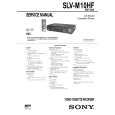
2-3. SERVO SYSTEM CHECK Unless otherwise specified, set the switches to the following positions. � � INPUT SELECT switch ........................................... LINE 1 TAPE SPEED switch ..................... SP (Remote commander)
2-3-1. RF Switching Position/ AF Switching Position Adjustments (MA-335 Board) [Adjustment Purpose] To adjust the link of the A-ch and B-ch of the tape playback outputs. To make the unit compatible with other tapes and units. If this specification is not satisfied, the link will appear on the screen and the screen will be disrupted, etc. Mode Signal Measurement point Playback Alignment tape: SP color bar portion CH1: Video LINE OUT (RF switching position) CN341 pin 1 (HF ADJ) (AF switching position) CH2: CN261 pin 3 (RF SWP) Oscilloscope 6.5 ± 0.5H (410 ± 32 µsec)
Measuring instrument Specified value
[Adjustment Method] 1) Short-circuit between JS161 and ground for about 1 second to activate the RF switching position adjustment mode. 2) Check that �AP� is indicated on FL display. 3) Using the channel + and � buttons, adjust to 410 ± 32 µsec (6.5 ± 0.5H). 4) Press the PAUSE button. (Adjustment is over for mono models.) 5) The set goes to the AF switching position adjustment mode.
Check that �AH� is indicated on FL display. Using the channel + and � buttons, minimize a chipped portion. At this time, confirm that a noisy sound is not heard. 8) Press the PAUSE button. 9) Check that �AH� indication is disappeared. When it is not disappeared, repeat from the item 1). 10) Press the STOP button. 11) Press the EJECT button.
CH2 RF SWP CN261 pin 3
6) 7)
CH1
Approx. 1Vp-p Approx. 5Vp-p V Enlarrgement Vertical sync. signal
CH2
OK CH1 REC AFM CN341 pin 1 NG
CH1
Should be minimized
CH2 CN261 pin 3
6.5 ± 0.5H
RF signal dropout
Fig. 6-2-3. Fig. 6-2-4.
6-3
|
|
|
> |
|