|
|
|
Categories
|
|
Information
|
|
Featured Product
|
|
|
 |
|
|
There are currently no product reviews.
 ;
Veramente completo, dettagliato e perfetto nella visione. Perfect, thanks!
 ;
Fully functional usable service manual. Considering the age of the manual and device quality was better than expected
;
Thank you very much, I've been very happy to find this manual on "Owner Manual". It's a perfect copy and it has been really useful for my work!
;
It took about 24-hours after my payment before I was able to get to the download. Apparently, payment processing is not 100% automated. That is no big deal, just be aware of that going in.
After I got to it, it was in good shape, easy to read, etc. Not some cheap FAX copy looking thing.
Also, this site was the cheapest I found. Another Plus!
;
Good price, very legible manual, exactly what I needed -- but had to wait a day to actually get the download of the manual. Would have preferred to download it immediately after payment rather than waiting for someone to "process" my order. I was surprised that I had to wait that long.
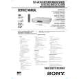
HiFi Switching Position Adjustment (MA-370 Board) [Adjustment Purpose] To adjust the link of the A-ch and B-ch of the tape playback outputs. To make the unit compatible with other tapes and units. If this specification is not satisfied, the link will appear on the screen and the screen will be disrupted, etc. Mode Signal Measurement point Measuring instrument Adjusting element Specified value Playback Alignment tape: SP color bar portion CH1: Pin 1 of CN270 (HF ADJ) CH2: Pin 3 of CN270 (RF SWP) Oscilloscope Remote Commander CH +/� B=minimize
2-4-2.
2-4-3. Normal Audio System Adjustment � Make adjustment in the SP mode unless otherwise specified. Use a normal VHS cassette for an adjustment tape. � Set AUDIO MONITOR to normal. 2-4-4. ACE Head Adjustment Refer to the VHS mechanical adjustment manual MECHANISM) (9-921-647-11).
(S
2-4-5. E-E Output Level Check [Adjustment purpose] Confirm that the output level adjust the reference input is within the specification. Mode Signal Measurement point Measuring instrument Specified value E-E 400 Hz, �7.5 dBs J561 L/R Audio level meter �7.5 ± 2 dBs
[Adjustment Method] 1) Check that �A H� is indicated on FL display. 2) 3) 4) 5) Adjust so that part B becomes minimized at CH +/�. Write data EEPROM by pressing PAUSE button. Check that �A H� indicator turns off. If �A H� indicator is still on, restart RF switching position Adjustment from the beginning.
B
[Check Method] 1) Input signal of 400 Hz and �7.5 dBs to the J561 L/R. 2) Check that the audio output level is �7.5 ± 2 dBs. 2-4-6. Frequency Response Check [Adjustment purpose] Confirm that the frequency characteristic is within the specification. Mode Signal Measurement point Measuring instrument Specified value REC and PB (SP mode) 400 Hz, �17.5 dBs 7 kHz, �17.5 dBs J561 L/R Audio level meter 0 ± 3 dB
CH1 HFADJ CH2 RF SWP
Note: Tape path adjustment must have been completed.
Fig. 6-2-5
[Confirmation Method] 1) Supply a signal of 400 Hz, �17.5 dBs to J561 L/R. 2) Connect the audio level meter to J561 L/R. 3) Adjust the attenuator so that the audio level meter will indicate �27.5 dBs. 4) Make recording in the SP mode. 5) Set an audio line input signal to 7 kHz and make recording. 6) Playback a recorded portion, and measure output levels at 400 Hz and 7 kHz. 7) Confirm that the 7 kHz playback output level within a range of the 400 Hz playback output level 0 ± 3 dB.
6-4
 $4.99 SLVN60 SONY
Owner's Manual Complete owner's manual in digital format. The manual will be available for download as PDF file aft…
|
|
|
> |
|