|
|
|
Categories
|
|
Information
|
|
Featured Product
|
|
|
 |
|
|
There are currently no product reviews.
 ;
Good manual contains all it takes to update, repair,these types of mixers.Thanks.
;
Great service. Fast response. High quality scan. Good price.
Thank you very much!!!
Oleg S.
;
Well-scanned, complete manual. Contains the information needed for repair and maintenance.
;
It's great to be able to obtain a precious technical information for a real old equipment. The one I got helps me a lot in the area of wiring diagram to repair my antique. PDF gave me clear enough information to find out thr details. Thanks for giving me the oppotunity to be able to access to almost vanished informations.
;
Another excellent aquisition. Fine detailed manual. Thanks
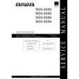
3-15. WHEEL GEAR 2, MAIN CAM AND MODE SWITCH (See Figs. 3-15-1 and 3-15-2)
1) Refer to section 3-2 and remove the mechanism unit. When you do this, make sure the mechanism is in EJECT mode. 2) Refer to section 3-7-1, then remove the harness mounting. 3) Remove the clamp 1, then remove the wheel gear 2 2. 4) Remove the washer 3, then remove the main cam 4. 5) After unscrewing the screw 5, remove the soldering from the terminal of the mode switch 6. 6) Remove the clamp 7, then remove the mode switch 6.
4 Main cam
3 Washer 6 Mode switch 5 Screw
2 Wheel gear 2
7 Clamp
ASSEMBLY NOTES:
1. Apply grease (VHJ-0100) to the shafts 8, 9 and 0, to the teeth of the main cam 4, and to the all over the cam groove of main cam 4. 2. When fitting the modes witch 6, align it in AB order as shown in Fig. 3-15-2. The alignment of the part B is shown in Fig. A. Position the teeth of the mode switch 6 so that the sixth tooth space left of part A is aligned with the triangular mark on the pinch cam gear !¡. After aligning part B, refer to section 3-9-2 and check the positioning of the mode switch, the pinch cam gear and the pinch lift cam. 3. Beforehand, remove the soldering from the soldered part of the MC-1 PWB assembly, in order to prevent the mode switch 6 being warped. Solder the mode switch 6 after tightening the screw 5 (See Fig. 3-15-1 ) . 4. Align the hole in the crescent slide !� with the hole in the mechanism chassis, as shown at point G in Fig. 315-2 (refer to section 3-16 and see the holes 5 and 6 in Fig. 3-16-1). 5. When fitting the main cam 4, position the mode switch 6 and the front rack gear !£ as shown at points C and D respectively in Fig. 3-15-2. 6. When fitting the gear wheel 2 2, position the main cam 4 and the wheel gear 1 !¢ as shown at points E and F respectively in Fig. 3-15-2.
!£ Front rack gear
!¡ Pinch cam gear 8 Shaft 9 Shaft
0 Shaft !� Crescent slide !¢ Wheel gear 1
Fig. 3-15-1
Fig. A
!¡ Pinch cam gear
Align at B
654 3 2
Marks on mode switch 6
1
B !£ Front rack gear D
6 Mode switch A C
Tooth tip on main cam 4
4 Main cam E
2 Wheel gear 2 F
!� Crescent slide G
!¢ Wheel gear 1
Fig. 3-15-2
5-22
|
|
|
> |
|