|
|
|
Categories
|
|
Information
|
|
Featured Product
|
|
|
 |
|
|
There are currently no product reviews.
 ;
Well.. I'd searched for this manual and although I found many copies online I was pleased to find your website with a well balanced pricing system and easy to search and follow links. That together with the very quick response time was just what I was looking for.. being a very impatient tech.. ;-) I had the service manual in front of me within a short time.
Bookmarked.. and you can bet I will always come here first for my service & user manuals..
best regards
Ed(Tony) Foley
G7WHK
;
I will definitely be back for more information when I need it.
;
The service manual when downloaded and printed out was clear and easy to read. I would have liked to have been able to enlarge some details, but this was not possible as the file permissions did not allow this. The service was very good. The time taken from placing my order to downloading the document was only a few minutes.
 ;
The manual is useful for trouble shooting for an old instrument. It saved money,and let me enjoy DIY.
;
Perfect source of information for replacing the HDD and performing general diagnostics.
SAFETY CHECK-OUT
After correcting the original service problem, perform the following safety checks before releasing the set to the customer.
1.
2. 3.
4.
5.
6. 7.
Check the area of your repair for unsoldered or poorly-soldered connections. Check the entire board surface for solder splashes and bridges. Check the interboard wiring to ensure that no wires are "pinched" or contact high-wattage resistors. Look for unauthorized replacement parts, particularly transistors, that were installed during a previous repair. Point them out to the customer and recommend their replacement. Look for parts which, though functioning, show obvious signs of deterioration. Point them out to the customer and recommend their replacement. Check the line cord for cracks and abrasion. Recommend the replacement of any such line cord to the customer. Check the B+ voltage to see it is at the values specified. Check the antenna terminals, metal trim, "metallized" knobs, screws, and all other exposed metal parts for AC leakage. Check leakage as described below.
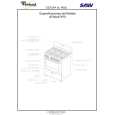
LEAKAGE TEST The AC leakage from any exposed metal part to earth ground and from all exposed metal parts to any exposed metal part having a return to chassis, must not exceed 0.5mA (500 microampers). Leakage current can be measured by any one of three methods. 1. A commercial leakage tester, such as the Simpson 229 or RCA TW-540A. Follow the manufacturers' instructions to use these instruments. A battery-operated AC milliammeter. The Data Precision 245 digital multimeter is suitable for this job. Measuring the voltage drop across a resistor by means of a VOM or battery-operated AC voltmeter. The "limit" indication is 0.75V, so analog meters must have an accurate low voltage scale. The Simpson 250 and Sanwa SH-63Trd are examples of a passive VOM that is suitable. Nearly all battery operated digital multimeters that have a 2V AC range are suitable. (See Fig. A)
2. 3.
To Exposed Metal Parts on Set
0.15 µF
1.5 k�
AC Voltmeter (0.75 V)
Earth Ground
Fig. A. Using an AC voltmeter to check AC leakage.
�3�
|
|
|
> |
|