|
|
|
Categories
|
|
Information
|
|
Featured Product
|
|
|
 |
|
|
There are currently no product reviews.
 ;
First class Service,
best quality, come again
Thank You.
vac
;
I didn't realise a manual for an early plasma TV such as the one we were gifted could be so easily obtained. No manual was supplied with it, and as senior citizens we were a little puzzled over some aspects of its use. I do not want a listing for your store credit as we are not fairly big computer users. The manual was well organised, as it should be, with its backing of the Pioneer name. The download was prompt and everything worked quite smoothly. Thank you. Gordon.
;
Thank you very much for the manual. It is what I needed and it will be very helpful to me. The delivery of the manual was easy and very fast. I strongly recommend this site to other users. Best regards.
 ;
Excellent!! Got what I need and very fast!! Thank You
;
Manual acquired with good resolution, complete in all its pages, very good policy of the folder where are saved all products purchased.
3.2
Removing the Speakers (See Fig.3)
� Remove the net assembly from the cabinet assembly. (See Fig.2.) (1) Remove the eight screws D attaching the two speakers. (2) Take out the two speakers from the cabinet assembly. (3) From the back side of the speakers, disconnect the speaker wires from the speaker terminals.
Cabinet assembly
Speaker terminal Speaker
D D
Speaker wires
Speaker wires Speaker Speaker terminal
Fig.3
3.3
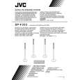
Removing the Center Speakers (See Fig.4)
(1) From the front side of the cabinet assembly, remove the six hooks c attaching the net assembly. (CAUTION) � When removing the net assembly, be careful not to damage the speakers and the cabinet assembly. (Reference) � As the net assembly is fixed with the adhesive and the two-sided tape, remove the net assembly by using a minus driver or similar tool. � Attach the net assembly after applying the adhesive to the hooks c. (2) Remove the eight screws E attaching the center speakers. (3) Take out the center speakers from the cabinet assembly. (4) From the back side of the center speakers, disconnect the speaker wires on the speaker terminals.
Cabinet assembly
Speaker wires Center speakers Hooks c
E E
Speaker wires Hooks c Hooks c Net assembly
Fig.4
Speaker terminal
1-6 (No.MB118)
 $4.99 SP-F303 JVC
Owner's Manual Complete owner's manual in digital format. The manual will be available for download as PDF file aft…
|
|
|
> |
|