|
|
|
Categories
|
|
Information
|
|
Featured Product
|
|
|
 |
|
|
There are currently no product reviews.
 ;
Probably it never existed a 1081 official service manual from Commodore, it's look more like a NAPCEC service manual & diagrams compilation of the 1084 series and his variants, like the nap6523, 8cm505, 1084S, 1084P and obviously the 1081. It's more complete than other scans and the quality of the scans also are far superior. It has two circuit diagrams variants of the 1081, mono and stereo versions. It doesn't include a diagram for the Philips CM8500 or CM8501, they look like the 1081 but they are slightly different.
 ;
Rapid, clear well done as all the scheme I downloaded from this site. Great job very functional and very useful
;
Great copy of the manual, has all information required for servicing,
;
I work at an authorized service center and I can tell if a manual is as it should be. This one is. It may be a scan, but a very good one at that. The interesting part for me was the curcuit diagram which was scanned at high quality, making it as good as the original. I will definitely be back as a customer. I need not say this, but I will: the price was the best. Thank you owner-manuals.com .
;
really a very good manual even sometimes the quality is no so good as before still very readible and very very useful!
SECTION 3 TEST MODE
BASE UNIT SECTION
MANUAL TEST MODE Set the Test Mode: 1. Set the DIAL MODE switch to �P� (pulse). 2. While pressing the HANDSET LOCATOR key, insert the AC adaptor (Reset start). 3. With the HANDSET LOCATOR key, still held down, switch the DIAL MODE switch �P� (pulse) n �T� (tone) n �P� (pulse). 4. When the HANDSET LOCATOR key is released, test mode starts. 5. Firstly, �0� will be dialled out at 10 pps. Then �1�, �4�, �8� and �#� will be sent out by DTMF. 6. Set to TX ON. Goes to external line state in 1 CH. Release the Test Mode: 1. Pull out the AC adaptor or turn off the power. MACHINE TEST MODE Set the Test Mode: 1. With one of the CH setting terminals in �H� input state, cause Reset of Power ON. Equipment enters machine test mode. 2. Setting of CH according to logic input with CH setting terminal. 3. ON/OFF of TX is according to the input logic of the DIAL MODE terminal. Release the Test Mode: 1. Pull out the AC adaptor or turn off the power. 2. Remove the short plug and turn on the power again.
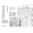
� base main board (conductor side) �
TP46
TP47
IC101
TP66 TP62 TP63 TP61 TP65 TP67 TP64 IC501
TP106
7
|
|
|
> |
|