|
|
|
Categories
|
|
Information
|
|
Featured Product
|
|
|
 |
|
|
There are currently no product reviews.
 ;
Manual was destroyed and this purchase made it possible to recover my manual . It was easy to down load and smooth to use thanks .
 ;
Turns out this was not the manual i was looking for. The concertmate 670 keyboard i have is a "Realistic" model made for Radio Shack and none of the diagrams on the owners manual i received matches up. HOWEVER, I must say the service Owners Manual provides was fast and efficient by being available online. The manual was in good readable condition and easily downloaded.
;
Great price, Quick delivery, the document was very usefull A+++++++++++++++
;
Thank´s for your help, I already recived these manual from you
;
Thank you for your manual It has the basic things to and i use the Oszi for Longer Time.
THX
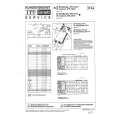
2) HANDSET
1. Test Mode Entry� Press �PGM� key and enter � TEST� on keypad. Alternative entry� Write 99h into LSB of location 9 in EEPROM. Exit� Press on �OFF� key. LCD test� Press the �7� key. Toggle TX power� Press the �0� key. Increment RF channel� Press the �#� key. 2. Test Equipment Required and Connection
3) BASE UNIT
1. Test Mode Entry� Simultaneously press the �HANDSET LOCATOR� key and toggle the �DIAL MODE� switch. When in test mode, the �IN USE� and �CHARGE� LEDs will be light on. Alternative entry� Write 99h into LSB of location 9 in EEPROM. Exit� Remove the AC power adaptor. Toggle TX power� DIAL MODE switch (S4001) T (TONE) position : TX ON P (PULSE) position : TX OFF Increment RF channel� Press the �HANDSET LOCATOR� key. 2. Test Equipment Required and Connection
C1029 C1030 � RF UNIT (HS) � J1 frequency counter � BASE MAIN BOARD (SIDE B) � � BASE MAIN BOARD (SIDE A) � frequency counter
� HAND MAIN BOARD � J1003
*
BATTERY 3.6V 48pin U1001
*
C1031 � RF UNIT (BU) �
J1 J1004
frequency counter
frequency counter
C4016 C4014 U4001 48pin
3. Verify Procedure Item 18.4MHz Frequency Error
Remark Connect the frequency counter to the test point J1, press �0� key to turn on the TX power. Then, check the frequency ± 1 kHz. If the result is within ± 1 kHz, then no adjustment required. Otherwise, refer to item 4. for Adjustment Procedure.
C4017
4. Adjustment Procedure Item 18.4MHz Frequency Error Adjustment Element C1030 Remark 1. Remove C1031 from the HAND MAIN board. 2. Solder an 20PF chip capacitor C1030 (1-164-160-11) on the HAND MAIN board (in parallel of C1029). 3. Connect the frequency counter to the U1001 pin rk. Adjust for 0 Hz ± 1 kHz.
3. Verify Procedure Item 18.4MHz Frequency Error
Remark Connect the frequency counter to the test point J1, press �0� key to turn on the TX power. Then, check the frequency ± 1 kHz. If the result is within ± 1 kHz, then no adjustment required. Otherwise, refer to item 4. for Adjustment Procedure.
4. Adjustment Procedure Item 18.4MHz Frequency Error
Adjustment Element C4016
Remark 1. Remove C4017 from the BASE MAIN board. 2. Solder an 20PF chip capacitor C4016 (1-164-160-11) on the BASE MAIN board (in parallel of C4014). 3. Connect the frequency counter to the U4001 pin rk. Adjust for 0 Hz ± 1 kHz.
�3�
�4�
 $4.99 SPPA973 SONY
Service Manual Complete service manual in digital format (PDF File). Service manuals usually contains circuit diagr…
|
|
|
> |
|