|
|
|
Categories
|
|
Information
|
|
Featured Product
|
|
|
 |
|
|
There are currently no product reviews.
 ;
Thanks to this service manual I repaired my old camcorder! The manual perfectly explains how to disassemble the camcorder step by step.
;
This manual is very useful because it presents the technical specifications of the cd player, including the manufacturer of the reader, this helps if you need to replace it. It also displays the settings and layout of the circuit.
;
Manual was a good representation of service infomation for the EWV404. It worked well for my repair.
 ;
Great quality copy, right what I was looking for, all I need to fix my radio.
Thanks
;
I BOUGHT A PAIR OF INFINITY VINTAGE SPEAKERS THAT REQUIRED TO BE REPAIRED AND THE ELECTRONIC TECHNICIAN ASKED ME FOR THE SERVICE MANUAL.
I TRIED TO GET IT AT THE MANUFACTURER'S SITE WITH NO SUCCESS, SO I STARTED TO LOOK FOR IT IN THE WEB FOR A LONG TIME, UNTIL I FOUND THE SERVICE MANUAL IN THIS EXCELLENT SITE "OWNER'S MANUAL.COM".
NOW I HAVE MY SPEAKERS WORKING AND ENJOYING THE MUSIC I LIKE.
THANKS TO "OWNER`S MANUAL.COM" I RECOMMEND THIS SITE TO EVERYONE.
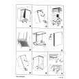
SECTION 5 ELECTRICAL ADJUSTMENTS
5-1. BASE UNIT SECTION
3. Checking TX Output Setting:
peak power meter
� Make the set in Test mode (see page 16) 1. Checking RX I&Q Output Level Setting:
oscilloscope + � level meter + � TP558: RXIP TP557: RXIN TP556: RXQP TP555: RXQN TP567: GND
SSG
+ �
ANTENNA TERMINAL
ANTENNA TERMINAL
Procedure: 1. Place the base unit in the Continuous Transmit more (CH1, High power). 2. Measure the ANT OUT output of the RF module in the base unit using a peak power meter. 3. Confirm that the measured output is 85 mW (MIN 30 mW). 4 .Also, execute steps 1 through 3 for the channels 10 and 20. CH10: 80 mW (MIN 25 mW) CH20: 80 mW (MIN 25 mW)
Procedure: 1. Place the base unit in the Continuous Receive mode (CHI, LNA ON, AGC ON). 2. Set the SSG frequency to the frequency on CHI + 300 kHz, and the RF output level to - 95 dBm. 3. Measure the output level of RXIN, RXIP, RXQN, and RXQP with a level meter. At this time, confirm with an oscilloscope that a sine wave of 300 kHz is output. 4. Confirm that the measured output level is -25.0 to -19.0 dB V. IF IC501 was replaced (there is no ID data), the output level is 30.0 to -24.0 dB V. 5. Also, execute steps 1 through 4 for the channels 10 and 20. * For the frequency on each channel, see page 13. 2. Checking TX Center Frequency Setting: � short: TP515� TP567 (GND)
frequency counter + � ANTENNA TERMINAL
Procedure: 1. Short TP515 (GND) and TP567 (GND) on the BASE MAIN board in the base unit. 2. Place the base unit in the Continuous Transmit more (CH1, High power). 3. Measure the ANT OUT frequency of the RF module in the base unit using a frequency counter. 4. Coufirm that the measured frequency is 904.200 MHz ± 27kHz. 5. Also, execute steps 1 through 4 for the channels 10 and 20.
22
|
|
|
> |
|