|
|
|
Categories
|
|
Information
|
|
Featured Product
|
|
|
 |
|
|
There are currently no product reviews.
 ;
Great manual, great price. Has a few of the basic operating instructions that most service manuals leave out. Complete instructions for disassembling board by board, safety precautions, schematics, complete parts list.
;
I am very pleased with the service manual for my RT-909. This was an easy purchase and great procuct, and much cheaper than other venues i had looked at. This web site is now listed in my favorites list. KEEP UP THE GOOD WORK. THANKS. J. BROWN
;
A very well written and easy to understand manual.
;
There was no problem at all.After paying i had to wait only a few hours,than i could
download the manual in best pdf-quality.
Thank You !
 ;
I found this service manual to be complete in every detail except for troubleshooting charts. It would be helpful if it had a set of troubleshooting charts; however it is a very good manual otherwise and for the price it is very well worth it.
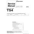
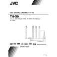
3.1.4 Removing the rear panel (See Fig.6) � Prior to performing the following procedures, remove the top cover assembly or metal cover. (1) From the back side of the main body, remove the twelve screws E and screw F attaching the rear panel. [For XVTHS9 and XV-THS7 models] (2) From the back side of the main body, remove the fourteen screws E and screw F attaching the rear panel. [For XVTHS8 model] (3) Release the engagement sections c and remove the rear panel from the main body. 3.1.5 Removing the audio signal I/O board (See Figs.7 and 8) � Prior to performing the following procedures, remove the top cover assembly or metal cover. (1) From the back side of the main body, remove the screw G and three screws H attaching the audio signal I/O board to the rear panel. (See Fig.7) (2) From the top side of the main body, remove the screw J attaching the audio signal I/O board to the chassis base. (See Fig.8) (3) Turn over the audio signal I/O board and disconnect the card wires from the connectors (CN441, CN442) on the forward side of the audio signal I/O board. (See Fig.8) 3.1.6 Removing the tuner (See Figs.7 to 9) � Prior to performing the following procedures, remove the top cover assembly or metal cover and audio signal I/O board. Reference: Disconnect the card wires from the connectors (CN441, CN442) on the audio signal I/O board as required. (See Fig.8.) (1) From the back side of the main body, remove the two screws K attaching the tuner to the rear panel. (See Fig.7) (2) From the top side of the main body, disconnect the card wire from the connector CN410 on the main board. (See Fig.9) (3) Take out the tuner from the main body. 3.1.7 Removing the DVD mechanism assembly (See Fig.9) � Prior to performing the following procedures, remove the top cover assembly or metal cover and audio signal I/O board. (1) From the top side of the main body, disconnect the card wires from the connectors (CN401 to CN403, CN408, CN409) on the main board. (2) Disconnect the card wire from the connector CN802 on the SD card board. [For TH-S9 and TH-S7 models] Reference: After connecting the card wire to the connector CN802 on the SD card board, fix the card wire with the spacers as before. (3) Remove the three screws L attaching the DVD mechanism assembly on the main body. (4) Take out the DVD mechanism assembly from the main body.
E [XV-THS8]
c
c
E
Rear panel
Fig.6
F
E
G
K
Rear panel
H
Fig.7
CN441 CN442
J
Audio signal input/output board Fig.8 SD board DVD mechanism assembly CN802 Spacer Spacer CN408
L
L
L
Main board
CN401 CN403 CN409 CN402 CN410
Fig.9
Tuner
(No.MB236)1-11
 $4.99 SP-PWS9 JVC
Owner's Manual Complete owner's manual in digital format. The manual will be available for download as PDF file aft…
|
|
|
> |
|