|
There are currently no product reviews.
 ;
Perfect manual, perfect service. Easy reading. Thanks a lot
;
Very good quality download here. Great hard to find manuals at a reasonable price.
 ;
I had a problem with the mains transformer, I did not know the voltages on the secondary, this manual helped me to solve this problem, thanks for the manual!
;
Great manual, great quality copy, complete parts reference and scematics, Thank you
;
Very good as always. Also this manual appears clear and well processed. I know it will help me to work on this TV. Thank you a lot! Matteo
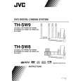
3.3.6 Removing the amp. board (See Fig.10) � Prior to performing the following procedures, remove the amplifier assembly, rear panel, heat sink BKT and mother board. (1) From the left side of the amplifier assembly, remove the nine screws J attaching the amp. board. (2) Take out the amp. board with the heat sink.
Amp. board
Heat sink
J
Fig.10 3.3.7 Removing the heat sink (See Figs.11 and 12) � Prior to performing the following procedures, remove the amplifier assembly, rear panel, heat sink BKT, mother board and amp. board. (1) From left side of the amp. board, remove the screw K attaching the hold spring to the heat sink. (See Fig.11.) (2) Remove the four screws L attaching the power IC to the heat sink. (See Fig.11.) (3) From the reverse side of the amp. board, remove the three screws M attaching the heat sink to the amp. board. (See Fig.12.) (4) Take out the heat sink. 3.3.8 Removing the power IC (See Fig. 12) � Prior to performing the following procedures, remove the amplifier assembly, rear panel, heat sink BKT, mother board, amp. board and heat sink. (1) From the reverse side of the amp. board, remove the solders from the solder points a on the amp. board. (2) Take out the power IC.
Heat sink
Power IC
Amp. board
L
Hold spring
Fig.11
L K
Amp. board
Solder points a
M
Fig.12
1-22 (No.MB236)
 $4.99 SP-THS9C JVC
Owner's Manual Complete owner's manual in digital format. The manual will be available for download as PDF file aft…
|