|
There are currently no product reviews.
 ;
The service manual was complete and the components on the drawings very good visible.
;
downloaded next day , manual is very helpful , fast and easy
 ;
This Service Manual was exactly what I needed to repair my Philips TV. The purchase was convenient and I received the manual at the same day I paid for it.
;
Very pleased with the whole process. Great commication and very easy instructions to order and to download the manual.
;
It's a good manual, this one it's a scan from the original factory service manual, great quality 100% readeable. definetely it worths what I paid for.
3.3.6 Removing the amp. board (See Fig.10) � Prior to performing the following procedures, remove the amplifier assembly, rear panel, heat sink BKT and mother board. (1) From the left side of the amplifier assembly, remove the nine screws J attaching the amp. board. (2) Take out the amp. board with the heat sink.
Amp. board
Heat sink
J
Fig.10 3.3.7 Removing the heat sink (See Figs.11 and 12) � Prior to performing the following procedures, remove the amplifier assembly, rear panel, heat sink BKT, mother board and amp. board. (1) From left side of the amp. board, remove the screw K attaching the hold spring to the heat sink. (See Fig.11.) (2) Remove the four screws L attaching the power IC to the heat sink. (See Fig.11.) (3) From the reverse side of the amp. board, remove the three screws M attaching the heat sink to the amp. board. (See Fig.12.) (4) Take out the heat sink. 3.3.8 Removing the power IC (See Fig. 12) � Prior to performing the following procedures, remove the amplifier assembly, rear panel, heat sink BKT, mother board, amp. board and heat sink. (1) From the reverse side of the amp. board, remove the solders from the solder points a on the amp. board. (2) Take out the power IC.
Heat sink
Power IC
Amp. board
L
Hold spring
Fig.11
L K
Amp. board
Solder points a
M
Fig.12
1-22 (No.MB236)
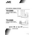 $4.99 SP-THS9F JVC
Owner's Manual Complete owner's manual in digital format. The manual will be available for download as PDF file aft…
|