|
|
|
Categories
|
|
Information
|
|
Featured Product
|
|
|
 |
|
|
There are currently no product reviews.
 ;
Irrespectively of this manual exist only germany language, it's useful - although i need some additional task to translate: My english is bad, but usable - but i really dont speak germany. :)
 ;
Excellent service from this company (including a total refund on an earlier purchase when through no fault of the company the manual was incomplete). I have purchased several manuals which I have been very satisfied with, as I am with this one. Highly recommended.
;
It was easy to order and received exactly what I needed. Only complaint would be the 24 hours you have to wait.
;
Manual was delivered in a timely manner and was all in English as advertised. The manuals I received when we moved into our flat were in German, Italian, and French. Having never used a steamer before, and not speaking/reading German very well, I needed an English Manual. this was a huge help.
;
Great Manual. This manual is available no where else. It was exactly what I was looking for. Only in German.
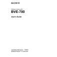
TH-A9R Removing the power amplifier board (B) (See Figs.9 and 11)
Prior to performing the following procedure, remove the heat sink cover, the amplifier assembly, the amplifier cover, the preamplifier board, the power supply & SP terminal board, the main amplifier board and power amplifier board (A). 1. Remove the four screws L attaching the power
Power amplifier board (B) Hooks Joint c
CN106
amplifier board (B) to the heat sink. 2. Release the four joint hooks c bent and attached to the outside of the power amplifier board (B). 3. Move the power amplifier board (B) in the direction of the arrow to release joint d and remove the power amplifier board (B) from the bracket (B).
CN105 Joint d Braket (B) Joint c
Fig.11
Main amplifier board
Removing the power transformer (See Figs.12 and 13)
Prior to performing the following procedure, remove the heat sink cover, the amplifier assembly, the amplifier cover, the preamplifier board, the power supply & SP terminal board, the main amplifier board, the power amplifier board (A) and power amplifier board (B). 1. Disconnect the harness from connector CN104 on the main amplifier board. 2. Disconnect the wire from connector CN107 on the power supply & SP terminal board. 3. Remove the four screws M attaching the power transformer.
Power supply & SP terminal board
M
CN104 CN108 CN107 Power transformer
N
Cord stopper N braket AC cord
M M
Fig.12
Removing the AC power cord (See Fig.12)
Prior to performing the following procedure, remove the heat sink cover, the amplifier assembly, the amplifier cover, the preamplifier board, the power supply & SP terminal board, the main amplidier board, the power amplifier board (A), the power amplifier board (B) and power transformer. 1. Disconnect the wire from connector CN108 on the power supply & SP terminal board.
CN110 Preamplifier board CN101
Power supply & SP terminal board
Main amplifier board CN111
2. Remove the two screws N attaching the AC power cord.
CN108 CN107
Fig.13 1-17
|
|
|
> |
|