|
|
|
Categories
|
|
Information
|
|
Featured Product
|
|
|
 |
|
|
There are currently no product reviews.
 ;
It was just what I needed. Thanks for your quick action and great price. You guys are top notch.
Thanks
 ;
Excellent manual, complete, great resolution, easy to read especially the schematics. Thank you !
;
Fast delivery, excellent resolution and complete. And above all, the best price ever !
;
Vielen Dank,
das war eine prima Sache. Habe das Serviceheft nach 3 Stunden herunterladen können. Qualität OK. Hat mir mit Erfolg bei der Fehlersuche und Reparatur meines
Nordmende Galaxy Mesa 9000 geholfen. Ich kann diesen Service bestens weiterempfehlen
A very good service.
Thank You!
;
everything i needed. it was easy to get. and this site is now my go to site for manuals.
6. ADJUSTMENT PROCEDURE
ALIGNMENT INSTRUCTIONS
(1) EQUIPMENT NEEDED AM Standard Signal Generator FM Standard Signal Generator Oscilloscope VTVM (AC,DC) AM Test Loop Antenna (AM Adjustment) FM Dummy Antenna (FM Adjustment) Stereo Signal Generator (RDS IN : EUROPE ONLY) Frequency Counter Distortion Analyser
AM-SG
IMPORTANT 1.Check power-source voltage. 2.Set the function switch to band aligned. 3.Keep the signal input as low as possible to adjust accurately. 4.Modulation and modulation frequency.
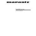
(2) FM, AM TRACKING VOLTAGE ADJUSTMENTS
AM,FM DC Voltmeter : Connect to test point TP1 and GND NO Band 1 2 FM AM AM Frequency 87.50 MHz 522 kHz 520 kHz Adjust for 1.6V 1.0V 1.0V Adjustment L7 L13 L13
DC EVM
(4) FM RF ADJUSTMENTS
Signal generator : Connect to FM Ant. (FM 75 ohm) through the dummy. Adjust for indication of VTVM of the wave form of scope to be maximum. Band NO FM 1 3 Frequency 100.10 MHz Adjust for
Max sensitivity
Adjustment L2,L5,L6,T1
Repeat steps 1 several times.
AC EVM OSCILLOSCOPE
Band AM
Item
Modulation 30 %
Modulation freq. 400 Hz 1 kHz
UNIT FM AM GND GND
kHz
FM (EUR, OVC) MONO : 40 kHz DEV. SR5000/N1B STERO : L=R (40 kHz), PILOT (7.5 kHz) 47.5 kHz DEV. SR5000/K1B RDS : STEREO + RDS (1.2 kHz) 48.7 kHz DEV. FM (USA) SR5000/U1B MONO : 75 kHz DEV. (100 %) DTEREO : L=R (67.5 kHz), PILOT (7.5 kHz)
TP1
AM LOOP antenna
60cm OUTPUT terminal
1 kHz
(3) AM RF ADJUSTMENTS
Signal generator : Connect to the AM Ant. Coil through the loop antenna. Adjust for the indication of VTVM of the wave form of scope to be maximum. /N1B, /K1B Band NO 1 AM 2 3
(5) FM MONO DISTORTION ADJUSTMENTS
Signal Generator : Connect to FM Ant. (FM 75 ohm) through the dummy. DC Voltmeter : Connect to TP2(+),TP3(-) through the choke coil (100uH). Distortion Meter : Connect to output L or R.
TUNER ADJUSTMENT POINT
Frequency 612 kHz
Adjust for
Max sensitivity
Adjustment L12,T13 Band NO FM 1 2 3 Frequency Adjust for Adjustment T11 T12
1503 kHz Max sensitivity CT1 Repeat steps 1 and 2 several times.
100.10 MHz DC Voltmeter 0V 100.10 MHz Minimum T.H.D
Repeat steps 1 and 2 several times.
AC EVM OSCILLOSCOPE
/U1B Band NO 1 AM 2 3 Frequency 610kHz 1510 kHz Adjust for
Max sensitivity Max sensitivity
Adjustment L12,T13 CT1
FM-SG
MHz OUT
Repeat steps 1 and 2 several times.
UNIT
DC EVM
FM Dummy
FM-SG
MHz OUT
FM 75ome in
UNIT
TP12 TP13 output Choke coil 100 H
OUTPUT
FM Dummy DISTORTION ANALYSER
FM 75ome in
37
38
|
|
|
> |
|