|
|
|
Categories
|
|
Information
|
|
Featured Product
|
|
|
 |
|
|
There are currently no product reviews.
 ;
Great quality complete service manual! complete parts list and drawings. Thanks!
;
Very good quality, prompt response. This website has reasonable prices and wide range of manuals that are hard to find.
;
The document was usefull, and it was exactly what I was looking for.
;
OK?..manual is complet and helpfull... for repairing such a old and rare boombox like JVC PCM it is necessary...
;
Super Anleitung. Ordentliche Auflösung. Das ganze noch in Deutsch wäre zu schön. Alle Datenblätter sind sauber Kopiert und alle Leitungswege sind sauber ausgeführt
SECTION 3 ELECTRICAL ADJUSTMENTS
TUNER SECTION
[FM] Setting ENT/BAND switch : FM Signal generator
FM RF signal generator 16� 0.01µF Set Headphones jack (J401) TP1(ANT) MAIN board Level meter
0 dB = 1 µV
FM TRACKING ADJUSTMENT Adjust for a maximum reading on level meter. L202 76.0MHz CT202 108.0MHz AM VCO ADJUSTMENT Adjust so that the voltage at TP3(LPF) becomes 2.60 ±0.05V. L205 531kHz AM IF ADJUSTMENT Adjust for a maximum reading on level meter. T201 450kHz AM TRACKING ADJUSTMENT Adjust for a maximum reading on level meter. L201 CT201 585kHz 1,485kHz
22.5 kHz frequency deviation by 400 Hz signal 30% Output level : as low as possible
[AM] Setting ENT/BAND switch : AM
AM RF signal generator
FM STEREO (76kHz) ADJUSTMENT
Adjustment point Frequency Indication Frequency counter Reading
Put the lead-wire antenna close to the set. Set
Level meter 16�
RV301
FM76MHz
76kHz ±200Hz
FM STEREO (76kHz) Procedure :
FM RF SSG
30% amplitude modulation by 400 Hz signal Output level : as low as possible
Headphones jack (J401) Digital Volt meter
0.01µF to TP1(ANT) Carrier frequency : 76MHz Modulation : no modulation Output level : 0.1V (100dB)
MAIN board TP3(LPF)
1. Connect frequency counter to the positions shown below. 2. Tune the set to 76MHz.
TP4(76kHz) 0.01µF Frequency counter + � Use a frequency counter having input impedance of 10M� or higher.
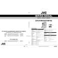
� Repeat the procedures in each adjustment several times for a maximum reading on level meter, and the frequency coverage and tracking adjustments should be finally done by the trimmer capacitors. Adjustment Location : � MAIN board (side A) �
� MAIN board (side B) �
TP4 (76kHz)
RV301 FM STEREO (76kHz) Adjustment
T201 AM IF Adjustment
L205 AM VCO Adjustment L201, CT201 AM Tracking Adjustment
TP3 (LPF) TP1 (ANT)
�4�
L202, CT202 FM Tracking Adjustment
|
|
|
> |
|