|
|
|
Categories
|
|
Information
|
|
Featured Product
|
|
|
 |
|
|
There are currently no product reviews.
 ;
A site where discontinualed schematic diagrams and back dated information can be found on discontinued radios tv's and any electronic equipment can be found. Newer manuals either Service and operating manuals. Radio amateurs should find this site a great source for ham radio equipment manuals. I will return to this site should I need information on any electrical equipment. priced easy to download in a PDF format and print pages need to undertake the repair.
;
Quality scan of the original. All the detail necessary to troubleshoot, repair and adjust the unit. I'm sure I will be downloading more manuals in the future as the need arises.
;
Exactly as described, a Service Manual complete with the schematics and PCB layout delivered in a timely manner. Many thanks for the great service.
 ;
some of the writing is a bit blur but the part in the schmatic was great and i have fixed the machine thanks
;
Well.. I'd searched for this manual and although I found many copies online I was pleased to find your website with a well balanced pricing system and easy to search and follow links. That together with the very quick response time was just what I was looking for.. being a very impatient tech.. ;-) I had the service manual in front of me within a short time.
Bookmarked.. and you can bet I will always come here first for my service & user manuals..
best regards
Ed(Tony) Foley
G7WHK
1
2
3
4
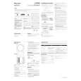
2.2 PANEL FACILITIES
FRONT PANEL
A
4 Crossover knob (CROSSOVER)
1
POWER ON
When using the subwoofer, set the upper frequency limit for the subwoofer (50 Hz to 200 Hz) so that it complements the output from your other speakers. When using the bass management features of an AV receiver, set to BYPASS ON in order to use the low-pass filter of the AV receiver for high quality sound.
5 Bypass switch (BYPASS)
When set to ON, the audio signal is routed directly to the woofer unit, bypassing the amplifier�s filter.
B
6 Phase switch (PHASE 0º /180º)
When set to 180º, the output phase becomes the reverse of the input signal, and when set to 0º, it is in the same phase as the input signal. � Normally, the switch is set to 0º. But when the sound connection between the subwoofer and the left and right speakers sounds unnatural, try switching to 180º and set the switch in the position where the sound is natural. � When using two or more subwoofers together, make sure that the phase switch of all of them are set to the same position.
1 Power Indicator (POWER ON)
Lights green when the power has been switched ON.
NOTE:
C
� If you are planning on switching the unit OFF for a long period of time, make sure to check that the indicator light has gone out after switching OFF.
7 Line Level Input terminal (LINE LEVEL INPUT)
Connect to the SUBWOOFER PREOUT terminal of an amplifier or receiver, with a RCA plug cord.
REAR PANEL
8 Line Level Output terminal (LINE LEVEL OUTPUT)
Used for connecting other equipment through the amplifier. The signal output from this jack is not affected in any way by the settings of the various controls on the unit.
D
9 AC IN
POWER VOLUME CROSSOVER
MAX MIN 200 Hz 50 Hz
2 3 4 5 6
� Connect the power cord to the powered subwoofer unit�s AC IN. � Connect the power cord to a AC socket.
BYPASS
ON OFF
PHASE
LINE LEVEL
OUTPUT INPUT AC IN
7 8 9
E
2 Power switch (POWER)
Switches the subwoofer between ON and OFF.
3 Volume knob (VOLUME)
Sets the subwoofer volume. � Turn the knob slowly from the MIN position. � With this unit, the bass level can be independently set, so do not turn up the bass on the AV amplifier.
F
6
1 2
S-RS3SW
3 4
|
|
|
> |
|