|
|
|
Categories
|
|
Information
|
|
Featured Product
|
|
|
 |
|
|
There are currently no product reviews.
 ;
Information was accurate and very helpful.
However the continuity made it a little difficult to follow from one page to the next.
 ;
Very very good as usual very trustable site. Perfect!!!!!!
;
The Service Manual received was helpful. Good copy of original document.. I recomend all of my friends about this technical page.
;
Perfect, complete manual, exactly what I needed. Recommended to everyone.
;
Very usefull manual. From my point of view there are needs more clearables images.
SECTION 2 MECHANISM
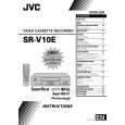
2.1 Before disassembling 2.1.1 Notes This model�s mechanism relates closely to the rotary encoder and system control circuit (the rotary encoder is meshed with the control cam). The system control circuit detects the mechanism condition using the rotary encoder�s phase (internal switch phase). Therefore, the parts such as the rotary encoder, control plate, loading gear and control cam need to be installed correctly in order for the mechanism to operate properly. (For the mechanism phase adjustment, refer to the installation of each part.) � For the disassembly procedure of the major parts of the main unit and notes, refer to the �section 1 disassembly�. � Before using a soldering iron, be sure to disconnect the power plug from the AC outlet. � Do not touch any of the adjustment points until a defect position is specified. � When plugging or unplugging the connector, be sure not to damage the wire. � Be sure the springs are hooked all the way around and in the correct direction. � When performing repairs, take care not to damage a catch, etc. 2.1.3 Setting the mechanism assembling mode The mechanism-assembling mode is provided with this mechanism. When disassembling and assembling, it is required to engage this mode. Set the mode by adopting the following procedures. (1) Remove the mechanism assembly using the disassembling procedure. (2) Turn gear (a) of the loading motor manually to set the mechanism assembly to the eject end mode. Make sure that the main deck is connected to the guide hole (a) of the drive lever and the seal (a) of the main deck is connected to the mark �E� of the control plate. This condition is called the mechanism-assembling mode.
Seal (a)
Guide hole (a)
�E� mark CONTROL PLATE DRIVE LEVER
<Example>
OK
(
NG not hooked all the way around
)
Fig. 2-1-1a
2.1.2 Mechanism operation check When the mechanism is operated without a cassette loaded, operate the mechanism in the mechanism service mode. (Refer to the "section 1 disassembly".)
LOADING MOTOR
Gear (a)
Unloading
Loading
Fig. 2-1-3a
2-1
 $4.99 SR-V10E JVC
Owner's Manual Complete owner's manual in digital format. The manual will be available for download as PDF file aft…
|
|
|
> |
|