|
|
|
Categories
|
|
Information
|
|
Featured Product
|
|
|
 |
|
|
There are currently no product reviews.
 ;
Manual was just as described!!! I odered it and in less than a day was able to download it and the text was clear and pages were all complete just as the original manual was. Purcashed this for a friend and they were more than happy. Perfect all around!
 ;
Excellent service and prompt delivery. But it's not a manual - only 4 pages wiring diagrams.
Thanks.
;
The manual I purchased was exactly what I needed to repair my Toshica television. The manual contained schematics and troubleshooting information that was very helpful.
;
Il download del Service Manual JVC HR 4100 non é stato eseguito
;
The Service Manual was just as expected, complete with schematics and I was able to download it in less than an hour after I ordered it. The only problem with these is that the schematics are hard to read due to the small font. I could remedy this by printing them on a larger printer.
SA-WSLF10/SS-CTL10/TSL10/TSL11 SECTION 4 ELECTRICAL ADJUSTMENT
DIAT SIGNAL RF LEVEL ADJUSTMENT This adjustment is performed in order to adjust the transmission distance of RF signal for DIAT communication. Connection:
oscilloscope TX board TP815 (RF AMP OUT)
Procedure: 1. Connect the oscilloscope to TP815 (RF AMP OUT) and GND on the TX board. 2. Connect DIR-T1 to DIR-T1 jack (J908). 3. Adjust RV801 on the TX board so that the center of waveform becomes trigger level 1.05 Vp-p. (*Trigger position: �4 DIV) 4. Confirm trigger is locked. 5. Adjust RV801 on the TX board so that the center of waveform becomes 2.2 to 2.4 Vp-p.
VOLT/DIV : 500 mV TIME/DIV : 500 ns
level : 2.2 to 2.4 Vp-p
RF Signal Reference Waveform
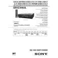
Adjustment Location:
� TX BOARD (Component Side) �
RV801 DIAT Signal RF Level Adjustment IC804 IC805
TP815 (RF AMP OUT)
8
|
|
|
> |
|