|
|
|
Categories
|
|
Information
|
|
Featured Product
|
|
|
 |
|
|
There are currently no product reviews.
 ;
Good scan, great price, but almost the same with the SV260 service manual.
;
This PDF is very comprehensive. It includes drawings, parts lists, schematics, pictures, PCB drawings, mechanical layouts, etc. for all three stackable equipment. The scans are good too. Easy to read and no smudges or black lines. I have no complaints. I will make this site my first stop for finding my service manuals.
 ;
This service manual includes drawings, schematics, exploded views, parts list, operating details, and more. Very good scans, very readable. The only thing that made it a 4 star rating was on approximately 4 scans only half of the page was scanned then the other half. I would have preferred the pages to be whole scans.
;
Good manual contains all it takes to update, repair,these types of mixers.Thanks.
;
Great service. Fast response. High quality scan. Good price.
Thank you very much!!!
Oleg S.
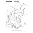
STANDARD NOTES FOR SERVICING
Circuit Board Indications
a. The output pin of the 3 pin Regulator ICs is indicated as shown. (2) Remove the flat pack-IC with tweezers while applying the hot air. (3) Bottom of the flat pack-IC is fixed with glue to the CBA; when removing entire flat pack-IC, first apply soldering iron to center of the flat pack-IC and heat up. Then remove (glue will be melted). (Fig. S-1-6) (4) Release the flat pack-IC from the CBA using tweezers. (Fig. S-1-6)
Top View Out In Input
Bottom View
b. For other ICs, pin 1 and every fifth pin are indicated as shown.
Caution:
1. Do not supply hot air to the chip parts around the flat pack-IC for over 6 seconds because damage to the chip parts may occur. Put masking tape around the flat pack-IC to protect other parts from damage. (Fig. S-1-2) 2. The flat pack-IC on the CBA is affixed with glue, so be careful not to break or damage the foil of each pin or the solder lands under the IC when removing it.
Hot-air Flat Pack-IC Desoldering Machine
5 Pin 1
10
c. The 1st pin of every male connector is indicated as shown.
Pin 1
CBA
How to Remove / Install Flat Pack-IC
1. Removal
With Hot-Air Flat Pack-IC Desoldering Machine: (1) Prepare the hot-air flat pack-IC desoldering machine, then apply hot air to the Flat Pack-IC (about 5 to 6 seconds). (Fig. S-1-1)
Masking Tape Tweezers Fig. S-1-2 Flat Pack-IC
Fig. S-1-1
3-1
L6115STA
|
|
|
> |
|