|
|
|
Categories
|
|
Information
|
|
Featured Product
|
|
|
 |
|
|
There are currently no product reviews.
 ;
muy buen manual por lo completo de este algunos esquemas estan muy divididos lo que hace algo dificil el seguimiento.
;
very good manual, with detail and clarity in esquematic diagrams and waveforms .
 ;
Very quality copy of original service manual, which contains the circuit diagrams, PCB and lists of components, well as recommendation for calibration procedures of device, also everything else, that need for repair, tuning and use this oscilloscope.
All presented copies have high-resolution, so you can view all in detail.
This manual will very useful for simple owners and for repairers.
I recommend these manual, because myself is owner of Philips PM3216 and I need sometimes servicing these oscilloscope (principally calibrating).
Also, these document is an example of excellent design of technical documentation.
;
Excellent printing quality.
A complete and very usefull service manual with all details.
GREAT SERVICE AT VERY LOW PRICE!
A+++++++++++++++++++++++++
;
manual excelente completo , diagramas y esquemas bien presentados y buena calidad de imagen.
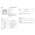
SECTION 2 DISASSEMBLY
SECTION 3 ELECTRICAL ADJUSTMENTS
Precautions in Repairing If the front unit fails, it is difficult to repair the inner circuits, so replace the entire front end unit. The FM TUNED level must be adjusted after the AM TUNED level adjustment has completed. AM SECTION
2 case
Note: Follow the disassembly procedure in the numerical order given.
1 two screws (case 3 TP2)
AM Tuning Level Adjustment Setting : BAND switch : MW(AM)
loop antenna AM RF signal generator loop antenna supplied accessories
set 30 % amplitude modulation by 400 Hz signal Carrier frequency : 999 kHz (at 9 k step) 1,000 kHz (at 10 k step) Output level : 25 dBµ
5 two screws (BVTP3 � 8)
AM antenna terminal 60 cm field strength dB(µV/m)= RF SSG output level dB (µV/m)�26 dB
3 flat wire (19 core) (CN102)
8 main board
1 two screws (case 3 TP2)
Procedure: 1. Set loop antenna A so that the loop antenna B input level becomes 55 dBµ/m. 2. Tune the set to 999 kHz or 1,000 kHz. 3. Adjust RV1 so that the TUNED indicator goes on. Adjustment Location : MAIN board. FM SECTION
4 three screws (BVTP3 � 10)
Adjustment Location : [MAIN BOARD] � Component Side �
RV2 FM Tuning Level Adjustment
CN101 FE2
TM1
FM Tuning Level Adjustment Setting : BAND switch : FM
FM RF Stereo signal generator
IC1
set
6 claw
Carrier frequency : 98 MHz Moduration : AUDIO 1kHz,75 kHz FM antenna terminal deviation (100%) (75 � coaxial) Output level : 26 dBµ (17.8 µV)
7 two claws
Procedure: 1. Tune the set to 98 MHz. 3. Adjust RV2 so that the TUNED indicator goes on. Adjustment Location : MAIN board.
CN102
RV1 AM Tuning Level Adjustment
�7�
�8�
|
|
|
> |
|