|
|
|
Categories
|
|
Information
|
|
Featured Product
|
|
|
 |
|
|
There are currently no product reviews.
 ;
Well done!!! I found what I need to have, indeed!
Furthermore, due to my hobby is repairing vintage equipments, I added this web site in my desk toolbar because I have in mind to search further service manuals. Thanks a lot www.owner-manuals.com !
Regards, Maurizio
;
Again very good service manual, this time very fast download. AAAAA+
;
Ckear manual, well reproduced with plenty of overlap on critical pages.
;
I buy the service manual cheaper here than in elsewhere.Am happy with this site. I recommended the Owner-Manuals.com
;
Great Manual. It was exactly what I was looking for
SAFETY CHECK-OUT
After correcting the original service problem, perform the following safety checks before releasing the set to the customer: Check the antenna terminals, metal trim, �metallized� knobs, screws, and all other exposed metal parts for AC leakage. Check leakage as described below.
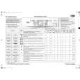
TABLE OF CONTENTS 1. GENERAL ·········································································· 4 2. TEST MODE ······································································ 6 3. DIAGRAMS
3-1. Block Diagram ······························································ 7 3-2. IC Block Diagrams ························································ 8 3-3. IC Pin Function Description ·········································· 8 3-4. Circuit Boards Location ················································ 9 3-5. Printed Wiring Board Main Section ·························· 10 3-6. Schematic Diagram Main Section (1/3) ···················· 11 3-7. Schematic Diagram Main Section (2/3) ···················· 12 3-8. Schematic Diagram Main Section (3/3) ···················· 13 3-9. Printed Wiring Board Panel Section ·························· 14 3-10. Schematic Diagram Panel Section ··························· 15 3-11. Printed Wiring Board Power Section ························ 16 3-12. Schematic Diagram Power Section ·························· 17 3-13. Printed Wiring Board Video Section ························· 18 3-14. Schematic Diagram Video Section ··························· 18
LEAKAGE
The AC leakage from any exposed metal part to earth ground and from all exposed metal parts to any exposed metal part having a return to chassis, must not exceed 0.5 mA (500 microamperes). Leakage current can be measured by any one of three methods. 1. A commercial leakage tester, such as the Simpson 229 or RCA WT-540A. Follow the manufacturers� instructions to use these instruments. A battery-operated AC milliammeter. The Data Precision 245 digital multimeter is suitable for this job. Measuring the voltage drop across a resistor by means of a VOM or battery-operated AC voltmeter. The �limit� indication is 0.75 V, so analog meters must have an accurate low-voltage scale. The Simpson 250 and Sanwa SH-63Trd are examples of a passive VOM that is suitable. Nearly all battery operated digital multimeters that have a 2V AC range are suitable. (See Fig. A)
To Exposed Metal Parts on Set
2.
3.
4. EXPLODED VIEWS
4-1. Front Panel Section ····················································· 19 4-2. Chassis Section ···························································· 20
5. ELECTRICAL PARTS LIST ······································· 21
0.15 µF
1.5 k�
AC Voltmeter (0.75 V)
Earth Ground Fig. A. Using an AC voltmeter to check AC leakage.
SAFETY-RELATED COMPONENT WARNING!! COMPONENTS IDENTIFIED BY MARK 0 OR DOTTED LINE WITH MARK 0 ON THE SCHEMATIC DIAGRAMS AND IN THE PARTS LIST ARE CRITICAL TO SAFE OPERATION. REPLACE THESE COMPONENTS WITH SONY PARTS WHOSE PART NUMBERS APPEAR AS SHOWN IN THIS MANUAL OR IN SUPPLEMENTS PUBLISHED BY SONY.
ATTENTION AU COMPOSANT AYANT RAPPORT � LA S�CURIT�! LES COMPOSANTS IDENTIF�S PAR UNE MARQUE 0 SUR LES DIAGRAMMES SCH�MATIQUES ET LA LISTE DES PI�CES SONT CRITIQUES POUR LA S�CURIT� DE FONCTIONNEMENT. NE REMPLACER CES COMPOSANTS QUE PAR DES PI�SES SONY DONT LES NUM�ROS SONT DONN�S DANS CE MANUEL OU DANS LES SUPP�MENTS PUBLI�S PAR SONY.
3
|
|
|
> |
|