|
|
|
Categories
|
|
Information
|
|
Featured Product
|
|
|
 |
|
|
There are currently no product reviews.
 ;
Very good detail, all pages clear, exactly what I needed
;
Excellent service, and just what I needed to service my TU-7700. All pages of the manual are clear and easily readable.
;
Excellent printing quality.
A complete and very usefull service manual with all details.
GREAT SERVICE AT VERY LOW PRICE!
A+++++++++++++++++++++++++
;
We received the manual in a timely manner and it was exactly what we were expecting. Excellent replacement for original Service Manual.
All schematics are very legible. We are really satisfied.
;
We received the manual in a timely manner and it was exactly what we were expecting. Excellent replacement for original Service Manual.
All schematics are very legible. We are really satisfied.
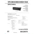
SECTION 2 SERVICING NOTE
Rear Panel
1 2 3 4 5 6 7
1. When the front panel is removed, the VR board is removed at the same time. Consequently the LEDs cannot be turned on and the sound volume cannot be increased or decreased from the remote control.
2. When servicing the DIGITAL board, be sure to connect the earth land of the DIGITAL board with the chassis frame so that the earth potential of the DIGITAL board must not be floated from the chassis frame.
8
SECTION 3 TEST MODE
FLUORESCENT INDICATOR TUBE TEST MODE
* All fluorescent segments are tested. When this test is activated, all segments turn on at the same time, then each segment turns on one after another. * Procedure: While depressing the ENTER, the LEVEL and the EQ buttons simultaneously, press the power [1/u] button to turn on the main power. All segments turn on at the same time, then each segment turns on press the ENTER button.
AM CHANNEL STEP 9 kHz/10 kHz SELECTION MODE (US,Canadian Model)
* Either the 9 kHz step or 10 kHz step can be selected for the AM channel step. * Procedure: Set the FUNCTION to AM. Turn off the main power. While depressing the TUNING+ button or the PRESET TUNING + button, press the power [1/u] button to turn on the main power. Either the message AM 9kHz Step or AM 10kHz Step appears. Select the desired step.
@¡
@º !ª
!�
!¶
!§ !�
!¢
!£
!�
!¡
0
9
FACTORY SET MODE
1 2 3 4 5 6 7 8 9 !º !¡ !� !£ ANTENNA DIGITAL 5.1 CH INPUT SPEAKERS (FRONT) SPEAKERS (REAR) SPEAKERS (CENTER) WOOFER INPEDANCE SELECTOR AC power cord AC OUTLET S-LINK 2ND AUDIO OUT VIDEO 1 !¢ !� VIDEO 2 DVD/LD (US, Canadian, Australian models) DVD (EXCEPT US, Canadian, Australian models) TV/SAT (US, Canadian, Australian models) TV/LD (EXCEPT US, Canadian, Australian models) TAPE (DE935 MODEL) MD/DAT (DE935 MODEL) MD/TAPE (EXCEPT DE935) CD PHONO MONITOR * All preset contents are reset to the default setting. * Procedure: While depressing the SET UP, the LEVEL and the ENTER buttons simultaneously, press the power [1/u] button to turn on the main power. The message Factry Set appears and the present contents are reset to the default values.
DSP TEST MODE
* It tests whether the DSP works correctly or not. When the DSP test is activated, the test data is output from the DSP (IC1401: CXD2712R) of the DIGITAL board and is written in the RAM (IC1402: IDT71V016S). When the test data is read from the RAM by the DSP, the data output must be equivalent to the original data. If they disagree, an error is triggered. Errors can be caused by the broken data line or defective soldering. * Procedure While pressing the SETUP, LEVEL and SUR buttons, press the POWER button to enter the DSP test mode. The message DSP TEST MODE appears. When an error occurs, the message DSP2 ERROR is displayed. When there is no error, the message DSP2 NO ERROR appears and the 1 kHz signal is output to all channels. Then, the mode can be switched the (SIGN WAVE) (THROUGH) and (INPULSE) mode.
!§
ALL CLEAR MODE
* All preset contents are cleared when this mode is activated. Use this mode before returning the product to clients upon completion of repair. * Procedure: While depressing the SET UP button simultaneously, press the power [1/u] button to turn on the main power. The machine enters the DEMO mode.DEMO mode: Wait a while, then the demonstration starts. If the power [1/u] button is pressed often the demonstration has started, the power is turned off, and the demonstration resumes if the power [1/u] button is pressed again. ALL CLEAR mode; If the power [1/u] button is pressed often the machine enters the DEMO mode, but before the demonstration starts, the display is turned off. Press [1/u] again. No response is returned. The press [1/u] again. The preset data is cleared and the machine enters the normal power-on state.
!¶ !� !ª @º @¡
VERSION MODE
* When this mode is used, the microprocessor version number is displayed. * Procedure: Press the POWER button while pressing the ENTER, LEVEL, and SUR buttons to turn on the power. The microprocessor version number appears as follows.
SOUND FIELD CLEAR MODE
* The preset sound field is cleared when this mode is activated. Use this mode before returning the product to clients upon completion of repair. * Procedure: While depressing the SOUND FIELD MODE button, press the power [1/u] button to turn on the main power. The message S.F Initialize appears and initialization is performed.
�5�
�6�
|
|
|
> |
|