|
|
|
Categories
|
|
Information
|
|
Featured Product
|
|
|
 |
|
|
There are currently no product reviews.
 ;
OK?..manual is complet and helpfull... for repairing such a old and rare boombox like JVC PCM it is necessary...
;
Super Anleitung. Ordentliche Auflösung. Das ganze noch in Deutsch wäre zu schön. Alle Datenblätter sind sauber Kopiert und alle Leitungswege sind sauber ausgeführt
;
Thanks God for the internet and thanks for the service like this - proffessional solution on time.
;
About the service it's very fast and reliable. About the manual the quality is high enough to read even the tiniest details on the wiring diagrams so you can't ask much more than that, let it alone for a manual of a product from 20 years ago. Thank you, very satisfied.
;
The downloaded quality was as good as the orignial
TABLE OF CONTENTS 1. SERVICING NOTE .......................................................... 3 2. GENERAL .......................................................................... 4 3. ELECTRICAL BLOCK CHECKING ...................... 5 4. DIAGRAMS
4-1. Circuit Boards Location ........................................................ 6 4-2. Schematic Diagram � Main (1/3) Section � .......................... 7 4-3. Schematic Diagram � Main (2/3) Section � .......................... 9 4-4. Schematic Diagram � Main (3/3) Section � ........................ 11 4-5. Printed Wiring Board � Main Section � .............................. 13 4-6. Printed Wiring Board � Display Section � .......................... 15 4-7. Schematic Diagram � Display Section � ............................ 17 4-8. Schematic Diagram � Panel Section � ................................ 19 4-9. Printed Wiring Board � Panel Section � .............................. 21 4-10. IC Block Diagrams ........................................................... 23 4-11. IC Pin Functions ............................................................... 26
5. EXPLODED VIEWS
5-1. Case Section ........................................................................ 28 5-2. Chassis Section ................................................................... 29
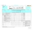
6. ELECTRICAL PARTS LIST ........................................ 30
SECTION 1 SERVICING NOTE
FACTORY SET
Mode which sets the preset settings of the unit to that at shipment. Procedure: While pressing the VIDEO button and TV/SAT button together, press the 1/u button to turn on the power. �FACTORY� will be displayed and factory settings executed.
INITIALIZATION
Mode which erases all the preset settings of the unit. Use this mode when returning the unit to the customer. Procedure: While pressing the VIDEO button, TV/SAT button, and TAPE/MD button together, press the 1/u button to turn on the power. �INITIAL� will be displayed and initialization executed.
FLUORESCENT INDICATOR TUBE LIGHTING CHECK
Mode which lights up the whole fluorescent indicator tube or partially. Procedure: While pressing the TV/SAT button and TAPE/MD button together, press the 1/u button to turn on the power. The fluorescent indicator tube will light up in about 0.5 seconds, and then start to light up partially. After partial lighting completes, the BASS BOOST indicator will light up, �FINISH� will be displayed, indicating that fluorescent indicator tube lighting check has completed.
SWITCHING OF 9 kHz/10 kHz AM CHANNEL STEP
The AM channels of this unit can be switched between 9 kHz and 10 kHz. Procedure: Set FUNCTION to AM and turn off the power. While pressing the TUNING + button, press the 1/u button to turn on the power. �9 k STEP� or �10 k STEP� will be displayed, and the channel step will be switched.
�3�
|
|
|
> |
|