|
|
|
Categories
|
|
Information
|
|
Featured Product
|
|
|
 |
|
|
There are currently no product reviews.
 ;
A manual hard to find. It was very helpful to restore my device.
;
I am very grateful for this manual. Without it could not repair my receiver.
;
excellent work as always you do cheap, fast net and clean. you do an incredible service......thanks!
;
Great Job even clear than the one before!!!! god organization- I'm always very satisfied
;
I'm very happy that you all are performing an incredible good job. Furthermore what you did is very useful for all people as me that have electronics as an hobby.Thank you!!!!!
Amplifier/Subwoofer
SUB125
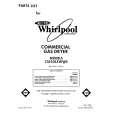
CONTROLS AND THEIR FUNCTION
1 2 3 4
SPEAKER LEVEL OUTPUT L C R
SPEAKER LEVEL INPUT L C R
ON
LINE LEVEL
INPUT
AUTO
SUBWOOFER LEVEL
L R
MIN MAX
5
SUB125
6
STAND BY
POWER
ON
7 8
AC 120V~,60Hz 160W
FUSE 2A/250V FUSE
9
1. Speaker Level Outputs - Connect the Left, Center and Right speakers to these connectors. 2. Speaker Level Inputs - These High Level Inputs are for receivers that do not have line-level �pre-amp out� or �subwoofer out� jacks. When a pair of main or satellite speakers are attached to the OUTPUT terminals, they are driven the full range of frequencies as generated by the music source (receiver, amplifier, etc.) 3. Line Level Input - These left and right Line Level Inputs are normally used when the receiver/ processor has line-level �pre-amp out � or �subwoofer out� jacks. 4. Auto/On Switch - This switch allows you to set the Mode of the Amplifier. Turn the switch to Auto to cause it to Auto-matically turn on when it receives a signal and Auto-matically turn off after twenty minutes without a signal. If this switch is left �On�, the subwoofer will always be ON when the power switch is turned On, regardless of input signal.
5. Subwoofer Level - This knob controls the volume level of the SUB125. 6. LED - Red & Green. The LEDs indicate the Mode status that the subwoofer is in. When the SUB125 is turned OFF neither LED will be lit. The Green LED will light when the SUB125 is ON and receiving a signal. The Red LED will light when the amplifier has not received a signal for twenty minutes. The subwoofer will turn on when your receiver/amplifier begins playing again. 7. Power Switch - This the master power switch. Use it (in Off mode) to disconnect power to the amplifier. 8. Fuse - Use only same type of fuses. For the U.S. 120V version use only a 2A 250V fuse. For the European 230V version use only a 1A fuse. 9. AC Cord
5
|
|
|
> |
|