Shopping cart is empty
 
English Polski Spanish 
Search For a Manual
 

(e.g. AA-V20EG JVC, ZX-7 Sony )
PayPal 1000+ rating Secure, Encrypted Checkout.
 
Categories
Information
Featured Product
Home >> OTHERS >> SVT User Guide
 
 0 item(s) in your cart 

AMPEG SVT
User Guide


Tweet about this product and get $1.00 of store credit for instant use!
  • Download
  • PDF Format
  • Complete manual
  • Language: English
Price: $4.99

Description of AMPEG SVT User Guide

It's a complete guide ( also known as operating manual or owner's manual), and it's in PDF format. After placing order we'll send You download instructions on Your email address.

The manual is available in languages: English

Not yet ready
You must purchase it first

Customer Reviews
There are currently no product reviews.

Text excerpt from page 4 (click to view)
SVTDI Vacuum Tube Direct Injection
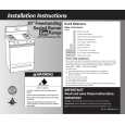
The Front Panel:

DIRECT TUBE

DIRECT TUBE

BALANCED OUTPUT

INPUT

THRU

0dB -6dB

GND LIFT

123

4

56

7

1. INPUT: Connect your line level signal here by means of a shielded signal cable terminated with a male 1/4� connector. 2. DIRECT/TUBE: This switch, when depressed, routes the input signal through the SVTDI�s tube stages before sending it to the Thru jack (#4). With this switch in the out position, the input signal is sent directly to the Thru jack, bypassing the buffer tube. 3. 0dB/-6dB: This switch, when depressed, attenuates the input signal by 6dB to compensate for active electronics or other �hot� input signals. With this switch in the out position, the input signal is at its full strength. 4. THRU: Use this jack to connect the output signal to its destination by means of a shielded signal cable terminated with a male 1/4� connector. 5. DIRECT/TUBE: This switch, when depressed, routes the input signal through the SVTDI�s tube stages before sending it to the Balanced Output jack (#7). With this switch in the out position, the input signal is sent directly to the Balanced Output jack, bypassing the buffer tube. 6. GND/LIFT: This switch, when depressed, lifts the signal ground at the Balanced Output jack (#7). This is helpful to eliminate hum in the output signal caused by ground loops. With this switch in the out position, the Balanced Output signal ground remains intact. 7. BALANCED OUTPUT: Use this jack to connect the output signal to its destination by means of a shielded signal cable terminated with a male XLR connector.
4

You might also want to buy

$4.99

SX-K700 TECHNICS
Owner's Manual

Complete owner's manual in digital format. The manual will be available for download as PDF file aft…

$4.99

CJ-V51 PIONEER
Service Manual

Complete service manual in digital format (PDF File). Service manuals usually contains circuit diagr…

$4.99

GRAND PRIX ELECTRONIC 754 BECKER
Service Manual

Complete service manual in digital format (PDF File). Service manuals usually contains circuit diagr…

$4.99

SX-PR602 TECHNICS
Service Manual

Complete service manual in digital format (PDF File). Service manuals usually contains circuit diagr…

$4.99

EV-S1000E SONY
Owner's Manual

Complete owner's manual in digital format. The manual will be available for download as PDF file aft…

$4.99

GRAND PRIX ELECTRONIC 780 BECKER
Service Manual

Complete service manual in digital format (PDF File). Service manuals usually contains circuit diagr…

$4.99

AG7330 PANASONIC
Service Manual

Complete service manual in digital format (PDF File). Service manuals usually contains circuit diagr…

$4.99

MECABLITZ 60 CT4 METZ
Service Manual

Complete service manual in digital format (PDF File). Service manuals usually contains circuit diagr…
>
Parse Time: 0.982 - Number of Queries: 120 - Query Time: 0.526