|
|
|
Categories
|
|
Information
|
|
Featured Product
|
|
|
 |
|
|
There are currently no product reviews.
 ;
This manual is very useful because it presents the technical specifications of the cd player, including the manufacturer of the reader, this helps if you need to replace it. It also displays the settings and layout of the circuit.
;
Manual was a good representation of service infomation for the EWV404. It worked well for my repair.
 ;
Great quality copy, right what I was looking for, all I need to fix my radio.
Thanks
;
I BOUGHT A PAIR OF INFINITY VINTAGE SPEAKERS THAT REQUIRED TO BE REPAIRED AND THE ELECTRONIC TECHNICIAN ASKED ME FOR THE SERVICE MANUAL.
I TRIED TO GET IT AT THE MANUFACTURER'S SITE WITH NO SUCCESS, SO I STARTED TO LOOK FOR IT IN THE WEB FOR A LONG TIME, UNTIL I FOUND THE SERVICE MANUAL IN THIS EXCELLENT SITE "OWNER'S MANUAL.COM".
NOW I HAVE MY SPEAKERS WORKING AND ENJOYING THE MUSIC I LIKE.
THANKS TO "OWNER`S MANUAL.COM" I RECOMMEND THIS SITE TO EVERYONE.
;
Very quick response. Very good and accurate print quality of the scanned document.
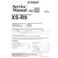
3-16. Crescent Slide
1. Refer to Section 3-2 and remove the mechanism unit. When you do this, make sure the mechanism is in EJECT mode. 2. Refer to Section 3-3-1 and remove the cassette mechanism assembly. 3. Refer to Section 3-7-2 and remove the capstan brake assembly. 4. Refer to Section 3-12-4 and remove the T soft brake assembly.
A 4 Crescent slide 6 Hole B 1 Screw
2 Crescent mounting
3 Clamp 0 Hole
8 Hole
C
5. Refer to Section 3-13-1 and remove the T brake act slide. 6. Refer to Section 3-12-1, then remove the reel belt and the reel pulley. 7. Refer to Section 3-15, then remove the wheel gear 2 and the main cam. 8. Refer to Section 3-13-2, then remove the wheel gear 1 and the brake control lever. 9. Remove the two screws 1, then remove the crescent mounting 2. 10. Remove the clamps 3, then raise the right end of the crescent slide 4 slightly. Slide the crescent slide 4 to the right until it comes away from the clamp 5, then remove it. Assembly Notes: 1. Apply grease (VHJ-0100) to the points A, B, C and D in Fig. 3-16-1, and to the crescent slide 4 shown in Fig. 3-16-2. 2. Before fitting the crescent slide 4, refer to Section 313-3 and align the arrow on the S brake act slide with the arrow on the mechanism chassis. Then refer to Fig. 3-17-3 and check that the S load gear and the T load gear have completed tape unloading. 3. When assembling the parts, raise the right side of the crescent slide 4 slightly, and keeping it in this position, slot the left side into the clamp 5, then align the hole 6 with the hole 7 in the mechanism chassis. When you do this, check that the hole 8 is aligned with the pin 9 on the BT spring lever assembly, and that the hole 0 is aligned with the pin !- on the S brake act slide, before pressing the crescent slide 4 into place. Check that the clamps 3 and 5 are engaged. 4. After assembly, check that each lever and each brake is working properly.
D 7 Hole 5 Clamp
9 Pin !- Pin
Fig. 3-16-1
Apply grease to the areas shown in � The places marked by dots should be greased particularly generously.
Grease the sides
Grease the teeth
Crescent slide
Fig. 3-16-2
SVT-RA40/RA168
2-29
|
|
|
> |
|