|
|
|
Categories
|
|
Information
|
|
Featured Product
|
|
|
 |
|
|
There are currently no product reviews.
 ;
Manuals were delivered promptly and were correct as advertised. No issues with the download link which was provided promptly after everything was processed. Very pleasant experience
;
Paid for service manual & got the download fast - worth a visit if you need a service manual
;
It's the manual, I am searching for. Now I am able to repair my Braun A501.
 ;
Great service manual. Unfortunately on page no. 41 there are some details which i can't read.
;
Wonderful service... doubt that I could have made the repairs to my turntable without this service manual. Great help!
Well worth the price paid!
1
2
3
4
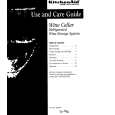
7.3 AMP BLOCK TROUBLE SHOOTING
The repair flow of the AMP section
A
PowerON After 4 seconds Level is low. A signal from CN481. (Sound from the speakers) no output no Go to SMPS part output Level is low. yes Check the screws OK of D AMP ASSY. Check soldering of IC421,441(B-2) Waveform is not normal.
The LED lights. yes
B
CrossOver 50Hz?
The speaker relay is on. yes Control Assy Input, D AMP Assy yes
no
A
Turn to Bypass and try again.
The 8-pin IC is hot.
no
Solder shorting? no yes
SMPS Assy Voltage of IC32? Less than [ 10V ]
Check other symptoms.
C
Replace the hot IC, since it is no longer serviceable.
Solder correction
Replace IC32.
'+''-' of multi-meter is reverse.
Cases other than 2�4 below. 1
A
D
Check the resistance between G and S of the FETs (Q421, 431, 441, and 451) with the multimeter. "+" is assigned to G and "-" is assigned to S for the multimeter. Multi-meter : ADVANTEST TR6847 or equivalent FET : IRFB23N15D 2 30k� to 40k� 1k to 10k 3 0 to 1k 4
All FETs are O.K.
All FETs are O.K.
FET has been broken.
E
Check soldering at IR2011S (IC421, IC441)
Replace IR2011S (IC421, IC441)
Replace IR2011S located on the same side as the FET with low resistance.
Everything is all right, except for the waveform (resistance of R471 and 472 is 10 ohms or more). Accidental failure mode Everything is all right, except for the relay not being turned on. Although the VOL is minimum, there is output from CN481.
F
Replace R471 and R472 with new ones. Replace Q506 and Q507 with new ones. Solder shorting of VR3141 of the CONTROL Assy.
44
1 2
S-W1EX
3 4
|
|
|
> |
|