|
|
|
Categories
|
|
Information
|
|
Featured Product
|
|
|
 |
|
|
There are currently no product reviews.
 ;
Detailed schematic diagram, manual for professionals
;
Good service manual,exploded view,adjusment and test point locations,head alignment,mechanical checks and adjusments,all perfect.
;
Block diagram,play rec block diagram,adjusments, it's a very good well done repair manual.
;
Very clear copy of the philips service manual. Fast delivery. Thank you very much
;
Excellent manual, detailed, very useful! Exactly what I needed, I'd recommend it to all who need it. Although images are scanned easily readable and explicit. A valuable tool product at a price more than modest, take it with confidence and you will not regret it!
1
2
3
4
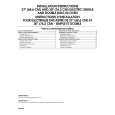
7. GENERAL INFORMATION
A
7.1 DISASSEMBLY 1. SUBWOOFER
¶ POWER AMP
2. SATELLITE
¶ Satellite Speakers are provided as assembly units. .
SECTION
Removing the AMP SECTION
Remove the 8 screws 1 from the power amplifier. Remove the connector lead, etc.
Screw1
B
Screw2
C
Removing the Operation Panel
Remove the 6 screws 2 from the power amplifier. Loosen the power lead.
A
AMP ASSY
B
OPERATION ASSY
D
Operation Panel
E
FRONT PANEL
The front panel is attached to the cabinet by its bosses applied with adhesive. To detach it, pry it open by inserting a flat blade screwdriver into bottom slot between the cabinet and front panel.
F
SPEAKER
To detach first remove the front panel, then remove the 4 external screws.
22
1 2
S-FCRW240B-S
3 4
|
|
|
> |
|