|
|
|
Categories
|
|
Information
|
|
Featured Product
|
|
|
 |
|
|
There are currently no product reviews.
 ;
Excellent printing quality.
A complete and very usefull service manual with all details.
GREAT SERVICE AT VERY LOW PRICE!
A++
;
Excellent printing quality.
A complete and very usefull service manual with all details.
GREAT SERVICE AT VERY LOW PRICE!
A+
;
Excellent printing quality.
A complete and very usefull service manual with all details.
GREAT SERVICE AT VERY LOW PRICE!
A++
;
Best help everywhere i got from here. My audio medicinman was happy to get this manual from me. So he could repair my pioneer perfectly. Thanks
R O
;
It was very usefull, it is clear the quality is super, the price I paid is very afordable.
Generally speaking Iam very happy with this company.
SERVICE ADJUSTMENT
No. Adjusting point
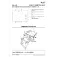
PURITY ADJUSTMENT
Adjusting procedure/conditions 1. Receive the GREEN-ONLY signal. Adjust the contrast control to have a beam current of about 700 µA. 2. Degauss the CRT enough with the degausing coil. Note: Follow the Job Instruction Sheet to adjust the magnetic field. Vertical Bv : +0.030 mT (0.30 gauss) Horizontal Bh: +0.020 mT (0.20 gauss) (See page 12.) 3. Maintain the purity magnet at the zero magnetic field and keep the static convergence roughly adjusted. 4. Observe the points �a� and �b� as shown in Fig. 2-1 through the microscope. Adjust the landing to the rank �A� requirements. 5. Adjust the raster rotation to 0 eastward. 6. Tighten up the deflection coil screws. » Tightening torque: 108 ±20 N (11 ±2 kgf) 7. Make sure the CRT corners landing meet the �A� rank requirements. If not, stick the magnet sheet to correct it. Note: This adjustment must be done after warming up the unit for 30 minutes or longer with a beam current over 500 µA 700 µA. Note: Set the service mode by TP1001 and TP1002 (short) then press factory process R/C RGB key to change to RGB mono colour mode. * For the following colours press R/C RGB key to change.
Green-only Blue-only Red-only
Waveform and others
PIF ADJUSTMENT
No. Adjusting point 1 RF-AGC check cut in adjustment (PRESETTED) Adjusting procedure/conditions 1. Receive �PAL COLOUR BAR� signal. » Signal Strength: 54 ± 1 dBµV (75 ohm open) 2. Connect the oscilloscope to TP210 (Tuner�s AGC Terminal) as shown in Fig. 1. Waveform and others Note: For the 50 ohm signal strength gauge, when not using 50/75 impedance adapter, signal strength is 52 ±1 dBµV(75 ohm open), instead of 54 ±1 dBµV (75 ohm open). precaution: The loss of using impedance adapter.
1
Purity adjustment
a
b
Fig. 2-1
Oscilloscope 0.1V + �
TV Set TP210
A
Bias box + �
» Bias box: About 4.5 V
B A=B
Fig. 1
3. Drop Input Signal strength to 51 ±1 dBµV (75 ohm open). 4. Under 1. and 3. conditions, the output voltage should be no change or below +0.1 V. In addition, change input signal strength to 57 ±2 dBµV, the output voltage should be no less than -0.1 V. 5. Change the antenna input signal to 63~67 dBµV, and make sure there is no noise. 6. Turn up the input signal to 90~95 dBµV to be sure that there is no cross modulation beat.
Fig. 2-2 Rank "A" (on the right of the CRT)
7
A
B A=B
Signal-colour screen cleared
Fig. 2-3
Rank "A" (on the left of the CRT)
* Press R/C RGB key for 1 second in NORMAL MODE, the colour will change to RGB mono colour mode. The TEXT Key �R. G. Cy� Key can be directly use to change to other colours screen.
SX-51J7
7-1
7-2
|
|
|
> |
|