|
There are currently no product reviews.
 ;
El producto satisface las necesidades del servicio t
;
This is a good quality scan of the Operation & Maintenance (Service) Manual for the PAL version of this high-band broadcast umatic, BVU-800P
All schematics and lineup procedures appear to be included in this one manual AFAICT.
The file size is just over 113 MB which gives an idea of the quality and number of pages.
All of the schematics, which contain some fairly small print, are easily readable when you zoom into the page.
John Thompson, Newcastle Upon Tyne, England.
;
Good quality, all schematics of few of models. There is also short form of user manual and regulation manual.
;
Perfect copy of the service manual. you can enlarge every page, and it comes up
with all details.
;
It´s very very nice manual with all, what i need. Original in good quality. Very fast business. Very much thanks...
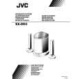
SX-DD3
Disassembly method
Removing the amplifier assembly (See Fig. 1~3)
1. Remove the eleven screws A attaching the amplifier assembly. 2. Pull out the amplifier assembly. 3. Remove the felt sheet from vibration prevention of the wire connector in the reverse side of the amplifier assembly. 4. Remove the connection of 3 wire connectors in the reverse side of the amplifier assembly.
Cabinet
A
A
A
Rear panel Fig. 1
Note: Before attaching the amplifier assembly the felt sheet is wound to the wire connector for the vibration prevention of the wire connector. Attaching the tie band from the top of the felt sheet.
A
Tie band
Removing the rear panel
Remove the amplifier assembly. 1. Remove the volume knob.
(See Fig. 4)
Felt sheet
2. Remove the three screws B attaching the rear panel .
Amp. assay
Vol. knob
Cabinet
Amp.
B
Cord connecter
Felt sheet
Fig. 4
Rear panel
Fig. 3
1-3
 $4.99 SX-DD3 JVC
Owner's Manual Complete owner's manual in digital format. The manual will be available for download as PDF file aft…
|