|
|
|
Categories
|
|
Information
|
|
Featured Product
|
|
|
 |
|
|
There are currently no product reviews.
 ;
The product was good and just what I needed, however I had moderate difficulty with the down load because the sight would not recognize my pass word. I was finally given a direct link to the manual and that worked.
 ;
Very quick and easy website to use and fast download of manual, quality of manual is excellent and will be pleased to use this service again in the future, thanks so much!
;
It is an very good and clear scanned service manual.
very recommended.
;
Easy to order the manual. Good quality and fast delivery.
;
The Service Manual for Sansui AU-9500 was very helpfull, in complete and in good printable condition.
Thanks.
2-3-5. Removal of the HP-65 Board (SX-M700/M100)
Procedure 1. Remove the top panel. (Refer to section, �2-1. REMOVAL OF THE EXTERNAL PANELS�.) 2. Remove the front panel assembly. (Refer to section, �21. REMOVAL OF THE EXTERNAL PANELS�.) 3. Remove the fixing nut securing the headphone jack. 4. Remove the fixing nut securing the volume control potentiometer.
Connector CN1 SX-M700 (from SW-722 board) HP-65 board Headphone jack Connector CN2 (from MT-105 board) SX-M100 (from AA-93 board)
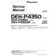
2-3-7. Removal of the VR-237 Board (SX-M700/M100)
Procedure 1. Remove the top panel. (Refer to section, �2-1. REMOVAL OF THE EXTERNAL PANELS�.) 2. Remove the front panel assembly. (Refer to section, �21. REMOVAL OF THE EXTERNAL PANELS�.) 3. Remove the four fixing nuts securing the volume control potentiometers. 4. Disconnect the connectors (CN1, CN2) from the VR-237 board.
VR-237 board
CN1 CN2 Volume control potentimeter
Volume control potentiometer
Fixing nuts
Fixing nuts
2-3-6. Removal of the SW-722 Board (SX-M700) 2-3-8. Removal of the SW-710 Board (SX-M700/M100)
Procedure 1. Remove the top panel. (Refer to section, �2-1. REMOVAL OF THE EXTERNAL PANELS�.) 2. Remove the front panel assembly. (Refer to section, �21. REMOVAL OF THE EXTERNAL PANELS�.) 3. Remove the selector knob. 4. Disconnect the connector (CN1) from the HP-65 board. 5. Remove the fixing nut securing the volume control potentiometer. 6. Disconnect the connector (CN2) from the SW-722 board.
Connector CN1 HP-65 board SW-722 board
Procedure 1. Remove the front panel assembly. (Refer to section, �21. REMOVAL OF THE EXTERNAL PANELS�.) 2. Disconnect the connector (CN1) from the SW-710 board. 3. Remove the two fixing screws (BVTP 3x8) securing the SW-710 board.
Volume control potentiometer Connector CN2 (from AA-93 board) Fixing nuts
Connector CN1 (from CPU-181 board) Screws (2 pcs) BVTP 3x8 SW-710 board
Selector knob
2-12(E)
SX-M700
|
|
|
> |
|