|
|
|
Categories
|
|
Information
|
|
Featured Product
|
|
|
 |
|
|
There are currently no product reviews.
 ;
Great product, helped me to restore vintage walkman cassette.
Just some pictures could be little bit more sharp and contrast
Thank you
;
I love older radio's and the service manuals that are sometimes hard to find. Was able to find a manual quite easily on this site.
;
Thank you for your shop manual! Your help was very useful - the device is repaired! Once again - Thank you! I wish you a successful business! Edward (Russia).
;
It was a great experience,instead of purchasing a new Stereo Amplifier ,in just minutes i repaired my old one and that was thaks to the manual I have purchased from you.
Thanks again.
Samuel Alter
;
Das ging ja sehr unkompliziert hat bestens geklappt und die Quallität ist auch noch gut.
Vielen Dank dafür.
Identifying parts and controls switch turns the display on and off. This connector inputs RGB video signals (0.700 Vp-p,
indicator lights up in green when monitor turned on. positive) and SYNC signals. The pin assignment is the same
SYSTEM CONNECTER (TO DISPLAY)
1 1 (Power) switch and indicator (pages 9, 17, 21) qg HD15 (RGB) input 2 connector (INPUT2) (page 8) Media engine
See the pages in parentheses for further details. The indicator lights up orange when the monitor is in power as qf . qh AC IN connector (page 9)
LCD display saving mode.
Front 2 MENU button (page 13) This connector provides AC power to the monitor.
INPUT 1
http://cxema.ru
This button displays the main menu. qj AC power switch (page 9)
AUDIO IN INPUT 2
3 6 (contrast) button (page 13) This switch turns media engine on and off. When the AC This button displays CONTRAST menu. power switch is turned on or off, the display automatically 4 8 (brightness) button (page 13) This button displays the BRITGHTNESS menu. qk AC power indicator (page 17) 5 2 (volume) +/� and M (+)/ m (�) buttons turned on. The indicator lights up in red when the display is (pages 10, 13) turned off with the media engine on. The indicator lights up in These buttons display VOLUME menu and function as orange when monitor is in the power saving mode. M (+)/ m (�) buttons when selecting the menu items and making adjustments. ql Media engine stand This stand is used to install the media engine vertically. 6 INPUT OK button, and indicator (pages 11, 13) qs AUDIO IN jack (page 10) signal. The signal and corresponding input indicator output jack of the computer or other audio equipment.
media engine lying flat block ventilation, and may cause a change each time you press this button. malfunction. This also functions as the OK button when displaying qd SYSTEM CONNECTOR (TO DISPLAY) (page 8)
turns on or off.
This indicator lights up in green when the media engine is
MENU
INPUT
1 2
CautionaudiothetoconnectingwhensignalsinputsjackThisinputvideo2INPUTor1selectsbutton
OK
Be sure to install media engine vertically shown as left. Installing the
menu on screen. This connector outputs signals to when the display and the media engine are connected with a system connecting GB cable. 7 SYSTEM CONNECTOR (page 8) This connector inputs signals from media engine when the display and the media engine are connected with a system qf HD15 (RGB) input 1 connector (INPUT1) (page 8) Rear/Side connecting cable. This connector inputs RGB video signals (0.700 Vp-p, positive) and SYNC signals. 8 Headphones jack (page 10) This jack outputs audio signals to the headphones. 5 4 3 2 1
1-2
10 9 8 7 6
9 Cable holder 15 14 13 12 11 This holder is used to keep the system connecting cable out of the way. 0 Security Lock Hole ( ) 1 Red The security lock hole should be applied with the Kensington Micro Saver Security System. 2 Green Micro Saver Security System is a trademark of Kensington. (Sync on Green) qa Display stand 4 ID (Ground) This stand is used to install the display. 5 DDC Ground* 6 Red Ground 7 Green Ground 8 Blue Ground 9 DDC + 5V* 10 Ground 11 ID (Ground) 12 Bi-Directional Data (SDA)* 13 H. Sync 14 V. Sync 15 Data Clock (SCL)*
* DDC (Display Data Channel) is a standard of VESA.
Pin No. Signal
3 Blue
6 7
 $4.99 TAM100 SONY
Owner's Manual Complete owner's manual in digital format. The manual will be available for download as PDF file aft… 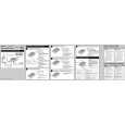 $4.99 TAM-100 SONY
Quick Start Quick start guide ( sometimes called quick guide ) contains most important information on how to use…
|
|
|
> |
|