|
There are currently no product reviews.
 ;
The manual was as described. Complete with parts list and technical information. Fast delivery.
 ;
Simple and fast...
The diagrams are clear and legible; i have been a great help.
The site is very reliable and precise thanks.
;
Very easy site. Great service and quick release for download. Manuals are of good quality.
Joop - The Netherlands
;
Very good manual, in depth and complete. Only criticism is that some of the circuit diagrams are slightly blurry and hard to follow for long periods of time, but this is to be expected. Perfect for any maintenance required. Also contains the wiring diagrams of the control cable for constructing extensions.
;
Received a quick response, material was exactly what it was supposed to be. The service did everything I expected it to do. would use service again.
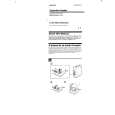
MAIN BOARD, MECHANISM DECK (MT-459V-118)
Note: On installation MAIN board adjust the S105 and knob (pause).
6 three screws
(IB lock)
7 claw
knob (pause)
8 mechanism deck (MT-459V-118)
1 Remove two solders of motor leads (M901).
S105
5 MAIN board 2 Remove the two solders 4 screw of the head lead (HRP901). (M1.4) 3 screw (1.7)
NOTE FOR INSTALLATION � MAIN BOARD
On installation MAIN board adjust the S101 and REC lever.
screw (M1.4) screw (1.7)
S101
REC lever
�4�
 $4.99 TCM-36 SONY
Owner's Manual Complete owner's manual in digital format. The manual will be available for download as PDF file aft…
|