|
There are currently no product reviews.
 ;
Excellent manual, complete, great resolution, easy to read especially the schematics. Thank you !
;
Fast delivery, excellent resolution and complete. And above all, the best price ever !
;
Vielen Dank,
das war eine prima Sache. Habe das Serviceheft nach 3 Stunden herunterladen können. Qualität OK. Hat mir mit Erfolg bei der Fehlersuche und Reparatur meines
Nordmende Galaxy Mesa 9000 geholfen. Ich kann diesen Service bestens weiterempfehlen
A very good service.
Thank You!
;
everything i needed. it was easy to get. and this site is now my go to site for manuals.
 ;
Quality as promised it arrived fast. No problems what so ever
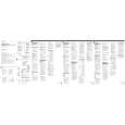
TCM-450DV SECTION 2 DISASSEMBLY
� This set can be disassembled in the order shown below.
Set
Cabinet (front) Cabinet (Rear)
Main board
Mechanism deck
Belt (Counter), Belt (CAP) S, M901 (Capstan/reel motor), HRP901 (REC/PB head), HE901 (ERASE head)
Cassette lid assy, LED board
Note: Follow the disassembly procedure in the numerical order given.
2-1. CABINET (REAR)
1 two screws (B1.7 X 9)
� On installation cabinet (rear), adjust the S501 and knob (VOR). S501
cabinet (front)
5 Remove solder on MAIN board (two places)
RV201 RV101
7 speaker (SP1) 6 two screws (B2.0)
4
MAIN board knob (VOR)
2 two screws (1.7 X 3)
knob (speed) sub assy � On installation cabinet (rear), adjust the RV201 and knob (speed) sub assy.
3 claw 8 cabinet (rear) knob (VOL) � On installation cabinet (rear), adjust the RV101 and knob (VOL).
3
|