|
|
|
Categories
|
|
Information
|
|
Featured Product
|
|
|
 |
|
|
There are currently no product reviews.
 ;
Perfect like it was descriped, Perfect like it was descriped
;
Very good detail, all pages clear, exactly what I needed
;
Excellent service, and just what I needed to service my TU-7700. All pages of the manual are clear and easily readable.
;
Excellent printing quality.
A complete and very usefull service manual with all details.
GREAT SERVICE AT VERY LOW PRICE!
A+++++++++++++++++++++++++
;
We received the manual in a timely manner and it was exactly what we were expecting. Excellent replacement for original Service Manual.
All schematics are very legible. We are really satisfied.
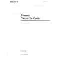
Record/Playback Head Azimuth Adjustment DECK A Procedure: 1. Forward Playback Mode
test tape P-4-A100 (10 kHz, �10 dB) 47 k� set level meter
DECK B
Tape speed Adjustment Adjust DECK A first Procedure: � Forward Playback Mode �
test tape WS-48B (3 kHz, 0 dB)
DECK A
DECK B
frequency counter 47 k� set
LINE OUT
LINE OUT
2. Turn the adjustment screw for the maximum output levels. If these levels do not match, turn the adjustment screw until both of output levels match together within 1 dB.
L-CH peak
output within 1 dB level
within 1 dB
(High speed adjustment) 1. Press the PITCH CONTROL button to set to OFF . 2. Set to test mode. (Refer to page 11.) 3. Press the · button to playback. 4. Press the HIGH/NORMAL button to playback at double speed. 5. Adjust RV316 (DECK A), RV416 (DECK B) so that the frequency counter reading becomes 5,980 ± 180 Hz. (Normal speed adjustment) 6. Press the · button to playback. 7. Press the HIGH/NORMAL button to playback at normal speed. 8. Adjust RV317 (DECK A), RV417 (DECK B) so that the frequency counter reading becomes 3,000 ± 90 Hz. (Pitch control adjustment) (DECK A) 9. Press the PITCH CONTROL button to set to ON . 10. Set PITCH CONTROL knob to mechanical center. 11. Press the · button to playback. 12. Adjust RV318 so that the frequency counter reading becomes 2,990 ± 90 Hz. Adjustment Location: MAIN board (See page 14.)
screw position
R-CH peak L-CH peak R-CH peak
screw position
3. Playback Mode
test tape P-4-A100 (10 kHz, �10 dB) L-CH 47 k�
oscilloscope
set
V
H
Sample value of wow and flutter W.RMS (JIS) less than 0.3% . (test tape : WS-48B) Playback Level Adjustment Procedure: � Forward Playback Mode �
test tape P-4-L300 (315 Hz, 0 dB) 47 k�
DECK A
DECK B
R-CH
47 k� LINE OUT Screen Pattern
level meter
In phase
45� good
90�
135�
180�
set
wrong
LINE OUT
4. Change the reverse playback mode and repeat the steps 1 to 3. 5. After the adjustment, lock the adjustment screws with suitable locking compound. Adjustment Location: � record/playback head �
Adjust DECK A : RV111 (L-CH), RV211 (R-CH) and DECK B : RV121 (L-CH), RV221 (R-CH) so the level meter reading becomes the adjustment limits below. Adjustment Value: LINE OUT level : �7.7 ± 0.5 dB (0.301 to 0.338 V) Level difference between channels : within 0.5 dB Confirm that the LINE OUT level does not change in playback mode while changing the mode from playback to stop several times.
reverse side
forward side
Adjustment Location: MAIN board (See page 14.)
adjustment screws
� 12 �
|
|
|
> |
|