|
There are currently no product reviews.
 ;
Good. Good. Good. Good. Good. Good. Good. Good. Good. Good. Good. Good. Good. Good.
 ;
Very helpfull information and I highly recommend this source for needed information about your products.
;
More than pleased with my prurchase, very good product for the price.
;
This is a good quality scan of the service manual which includes an assembly diagram, block diagram, schematic, and parts list. Exactly what is needed to repair my KR-V55R receiver.
;
Excellent concise manual. All needed information was included. Typeface and diagrams were clear. Very fair price considering what others are charging. Many thanks
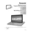
TH-37PHD8GK / TH-37PHD8GS / TH-37PHD8UK / TH-42PHD8GK / TH-42PHD8GS / TH-42PHD8UK
15. Disconnect the couplers(SC45, SC46). 16. Remove the each 2 screws and then slide the SU-Board and the SD-Board to the left.
20. Disconnect the coupler(SS23). 21. Remove the Flexible Cable from the coupler(SS55). 22. Remove the 2 screws and then remove the SS2-Board . 23. Disconnect the coupler(SS22). 24. Remove the Flexible Cable from the coupler(SS56). 25. Remove the 2 screws and then remove the SS3-Board. 26. Disconnect the couplers(SS24, SS32, SS34). 27. Remove the Flexible Cable from the couplers(SS52, SS53). 28. Remove the 6 screws and then remove the SS-Board.
17. Remove the Flexible Cable from the couplers(SU1, SU2, SU3, SU4) and then remove the SU-Board. 18. Remove the Flexible Cable from the couplers(SD1, SD2, SD3, SD4) and then remove the SD-Board.
29. Disconnect the coupler(C12). 30. Remove the 8 screws and then remove the Flexible Cable from the couplers(CA1, CA2, CA3, CA4). 31. Remove the 3 screws and then remove the C1-Board.
19. Remove the 6 screws and then remove the SC-Board.
32. Remove the 8 screws and then remove the Flexible Cable from the couplers(CA5, CA6, CA7, CA8). 33. Remove the 3 screws and then remove the C2-Board.
31
|