|
There are currently no product reviews.
 ;
This is the correct service manual of SHARP RX-100H(BK) DAT.
;
The ervice manual for my 1982 Kenwood KR-1000 receiver is great! Full detail on all circuits with part number detail. I will definately be ordering more manuals for my other vintage equipment! Order was fulfilled quickly! Very efficient ordering process! Thnaks for your help! Great site!
 ;
Everything in the manual was excellent except for a couple of pictures of specific areas in the unit that were a little dark. Owners Manuals re-sent the pdf file & the problem was corrected. Excellent product! George
;
Thanks for offering this item at such a good price. Proved handy in identifying the part I was looking for my set.
Thanks again.
;
This is the original manufacturers service manual, with detailed info on the circit boards, explosion drawings of all parts in assembly order, and tuning instructions. The only thing missing is the information on the dimensions of the various drive belts. mail me if you need them. gcrossman_at_aol.com
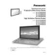
TH-37PHD8GK / TH-37PHD8GS / TH-37PHD8UK / TH-42PHD8GK / TH-42PHD8GS / TH-42PHD8UK
15. Disconnect the couplers(SC45, SC46). 16. Remove the each 2 screws and then slide the SU-Board and the SD-Board to the left.
20. Disconnect the coupler(SS23). 21. Remove the Flexible Cable from the coupler(SS55). 22. Remove the 2 screws and then remove the SS2-Board . 23. Disconnect the coupler(SS22). 24. Remove the Flexible Cable from the coupler(SS56). 25. Remove the 2 screws and then remove the SS3-Board. 26. Disconnect the couplers(SS24, SS32, SS34). 27. Remove the Flexible Cable from the couplers(SS52, SS53). 28. Remove the 6 screws and then remove the SS-Board.
17. Remove the Flexible Cable from the couplers(SU1, SU2, SU3, SU4) and then remove the SU-Board. 18. Remove the Flexible Cable from the couplers(SD1, SD2, SD3, SD4) and then remove the SD-Board.
29. Disconnect the coupler(C12). 30. Remove the 8 screws and then remove the Flexible Cable from the couplers(CA1, CA2, CA3, CA4). 31. Remove the 3 screws and then remove the C1-Board.
19. Remove the 6 screws and then remove the SC-Board.
32. Remove the 8 screws and then remove the Flexible Cable from the couplers(CA5, CA6, CA7, CA8). 33. Remove the 3 screws and then remove the C2-Board.
31
|