|
There are currently no product reviews.
 ;
This service manual includes drawings, schematics, exploded views, parts list, operating details, and more. Very good scans, very readable. The only thing that made it a 4 star rating was on approximately 4 scans only half of the page was scanned then the other half. I would have preferred the pages to be whole scans.
 ;
Good manual contains all it takes to update, repair,these types of mixers.Thanks.
;
Great service. Fast response. High quality scan. Good price.
Thank you very much!!!
Oleg S.
;
Well-scanned, complete manual. Contains the information needed for repair and maintenance.
;
It's great to be able to obtain a precious technical information for a real old equipment. The one I got helps me a lot in the area of wiring diagram to repair my antique. PDF gave me clear enough information to find out thr details. Thanks for giving me the oppotunity to be able to access to almost vanished informations.
TH-A10R/TH-A10
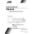
Removing the eject board (See Fig.28)
1. Disconnect the harness from connector CN702 on the eject board. 2. Remove the three screws P board. attaching the eject
Eject board Switch board
P
Removing the LCD board (See Fig.29)
1. Remove the four screws Q attaching the LCD board. 2. Unsolder WA701, WA703 and WA704 on the LCD board.
CN702
T
Fig.28
Q
Removing the IC board (See Fig.27)
1. Remove the screw R attaching the IC board. 2. Disconnect the harness from connector CN706 on the IC board.
WA701 LCD board
Q
WA704 WA703
Q
Removing the LED board (See Fig.27)
Prior to performing the following procedure, remove the LCD board and the IC board. 1. Disconnect the harness from connector CN705 on the power switch board. 2. Remove the two screws S attaching the LED board. Fig.29
Q
IC board
R
CN706 Power switch board
O O
Removing the switch board (See Fig.28)
Prior to performing the following procedure, remove the LCD board.
S
1. Disconnect the harness from connector CN702 on the eject board. 2. Remove the two screws T board. attaching the switch Fig.27
LED board
1-12
 $4.99 TH-A10 JVC
Owner's Manual Complete owner's manual in digital format. The manual will be available for download as PDF file aft…
|