|
There are currently no product reviews.
 ;
It is OK, this manual help me to repair my dynacord
 ;
Good manual. Even it is an old printed manual, it is well scanned and complete, with all drawings, schematics and parts list. Very good return for the cost.
;
I'm very satisfied with my purchase. It resolved my problem. Owner-manuals.com is a very very good place.
Thank you!
;
Veramente completo, dettagliato e perfetto nella visione. Perfect, thanks!
;
Fully functional usable service manual. Considering the age of the manual and device quality was better than expected
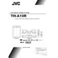
TH-A10R/TH-A10
Removing the eject board (See Fig.28)
1. Disconnect the harness from connector CN702 on the eject board. 2. Remove the three screws P board. attaching the eject
Eject board Switch board
P
Removing the LCD board (See Fig.29)
1. Remove the four screws Q attaching the LCD board. 2. Unsolder WA701, WA703 and WA704 on the LCD board.
CN702
T
Fig.28
Q
Removing the IC board (See Fig.27)
1. Remove the screw R attaching the IC board. 2. Disconnect the harness from connector CN706 on the IC board.
WA701 LCD board
Q
WA704 WA703
Q
Removing the LED board (See Fig.27)
Prior to performing the following procedure, remove the LCD board and the IC board. 1. Disconnect the harness from connector CN705 on the power switch board. 2. Remove the two screws S attaching the LED board. Fig.29
Q
IC board
R
CN706 Power switch board
O O
Removing the switch board (See Fig.28)
Prior to performing the following procedure, remove the LCD board.
S
1. Disconnect the harness from connector CN702 on the eject board. 2. Remove the two screws T board. attaching the switch Fig.27
LED board
1-12
 $4.99 THA10R JVC
Owner's Manual Complete owner's manual in digital format. The manual will be available for download as PDF file aft…
|