|
There are currently no product reviews.
 ;
I'm very satisfied with my purchase. It resolved my problem. Owner-manuals.com is a very very good place.
Thank you!
 ;
Veramente completo, dettagliato e perfetto nella visione. Perfect, thanks!
;
Fully functional usable service manual. Considering the age of the manual and device quality was better than expected
;
Thank you very much, I've been very happy to find this manual on "Owner Manual". It's a perfect copy and it has been really useful for my work!
;
It took about 24-hours after my payment before I was able to get to the download. Apparently, payment processing is not 100% automated. That is no big deal, just be aware of that going in.
After I got to it, it was in good shape, easy to read, etc. Not some cheap FAX copy looking thing.
Also, this site was the cheapest I found. Another Plus!
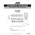
3.1.10 Removing the main board (See Fig.14) � Prior to performing the following procedures, remove the top cover, tray door, DVD mechanism assembly, fan motor, rear panel, video board and function board. (1) From the top side of the main body, remove the nine screws P attaching the main board. (2) Disconnect the wires from the connectors ACW2, ACW3, ACW4 and ACW5 on the main board and take out the main board. Reference: � When attaching the screw P, attach the wire clamp together with it. � After connecting the wire to the connector ACW2, bundle the wire using the wire clamp.
Power trans
Q
Wire clamp
Q
ACW4
P
ACW3 ACW5
ACW2
P
3.1.11 Removing the power trans (See Fig.14) � Prior to performing the following procedures, remove the top cover, tray door, DVD mechanism assembly, fan motor, rear panel, video board and function board. (1) From the top side of the main body, disconnect the wires from the connectors ACW2, ACW3, ACW4 and ACW5 on the main board. (2) Remove the four screws Q attaching the power trans.
P
Fig.14
(No.MB141)1-11
 $4.99 TH-A25 JVC
Circuit Diagrams Set of circuit diagrams. The diagrams will be provided as PDF file. The file will be delivered after…  $4.99 TH-A25 JVC
Owner's Manual Complete owner's manual in digital format. The manual will be available for download as PDF file aft…  $4.99 TH-A25 JVC
Parts Catalog Parts Catalog only. It's available in PDF format. Useful, if Your equipment is broken and You need t…
|