|
|
|
Categories
|
|
Information
|
|
Featured Product
|
|
|
 |
|
|
There are currently no product reviews.
 ;
It was magic after so many years to still be able to source this info. It was equally amazing to return my Pioneer receiver to it near new sound quality AFTER NEARLY 30 YEARS! Thank you for this ability!
;
Very quick and easy website to use and fast download of manual, quality of manual is excellent and will be pleased to use this service again in the future, thanks so much!
 ;
Easy and secure way to get a complete service manual of a vintage hifi component. Only some parts of the print copy are dificult to read. Nice price!
;
The manual is an excellent reproduction with complete schematics, made troubleshooting and repair a simple process.
;
Up to now you are the BEST! Prompt-efficient and so reasonable ! I have been after SONY service manual for quite some time !Thank you very much ! I can recomend your service to
all my collegagues ! V.Bergfield .
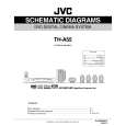
3.1.6 Removing the DSP board (See Figs.9 and 10) � Prior to performing the following procedures, remove the top panel and rear cover. (1) From the top side of the DSP board, disconnect the card wires from the connectors CN401 on the DSP board. (See Fig.10) (2) Remove the screw K attaching the DSP board from the section d of the barrier. (See Fig.10) (3) From the back side of the main body, remove the screw L and two screws M attaching the DSP board. (See Fig.9) Reference: � When attaching the DSP board, hang the DSP board on the section d of the barrier. (See Fig.10)
L
M
N
Fig.9
Rear panel
Section d
3.1.7 Removing the tuner (See Figs.9 and 11) � Prior to performing the following procedures, remove the top panel, rear cover and DSP board. (1) From the top side of the tuner, disconnect the card wire from the connector CN1 on the tuner. (See Fig.11) (2) From the back side of the main body, remove the two screws N attaching the tuner. (See Fig.9) (3) Take out the tuner from the main body.
K
CN401
DSP board
Fig.10
Tuner
Fig.11
CN1
(No.MB055)1-9
 $4.99 TH-A55 JVC
Circuit Diagrams Set of circuit diagrams. The diagrams will be provided as PDF file. The file will be delivered after… 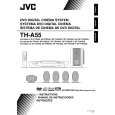 $4.99 TH-A55 JVC
Owner's Manual Complete owner's manual in digital format. The manual will be available for download as PDF file aft…  $4.99 TH-A55 JVC
Parts Catalog Parts Catalog only. It's available in PDF format. Useful, if Your equipment is broken and You need t…
|
|
|
> |
|


